双极性步进电机(下):微步进与衰减模式

概述
在本系列的上一篇文章中,我们介绍了双极性步进电机的三种控制模式及其机械结构,其中包括双全桥驱动器。本文将讨论双极性步进电机的微步进模式,以及它如何控制双全桥驱动器。
微步进
半步步进模式作为单相步进和整步步进的结合,可以获得更多的电气角度位置。而微步进则增加了更多的中间角度位置,实现了更精细的步进。
图 1 显示了微步进的八个细分角度。它将单相步进的90°电角分为八等份,分别代表八个电流位置。每个位置的电流都是A相绕组和B相绕组的电流合成矢量。合成矢量的幅度始终为 1。
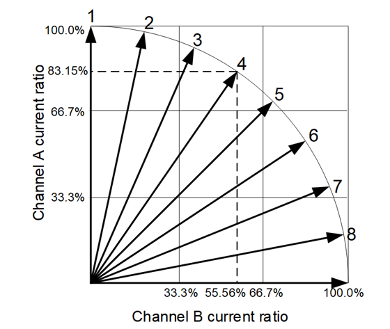
图 1:八个电气角度
每个位置的电流都需要分别投射到A相和B相上,以获得相应控制值(见表1)。
表 1:八步微步进值
| 步进模式 | 相对电流电平序列 (%) | 电流位置 | |
| A相 | B相 | ||
| 八步 | 100 | 0 | 1 |
| 98.08 | 19.51 | 2 | |
| 92.39 | 38.27 | 3 | |
| 83.15 | 55.56 | 4 | |
| 70.71 | 70.71 | 5 | |
| 55.56 | 83.15 | 6 | |
| 38.27 | 92.39 | 7 | |
| 19.51 | 98.08 | 8 | |
相关内容
A相和B相电流可以根据表1中的相应值进行控制。通过对电流的控制,可以实现在相应角度合成A相与B相的电流矢量。
在八个分段(或阶跃)的控制下,双极性步进电机的电流已经类似于正弦波(见图 2)。 如果阶跃更多,通过双极性步进电机绕组的电流将更加趋近于标准正弦波。正弦电流波形可以减小电机输出的扭矩脉动,并在空中形成圆形旋转磁场,从而提高步进电机的旋转稳定性。
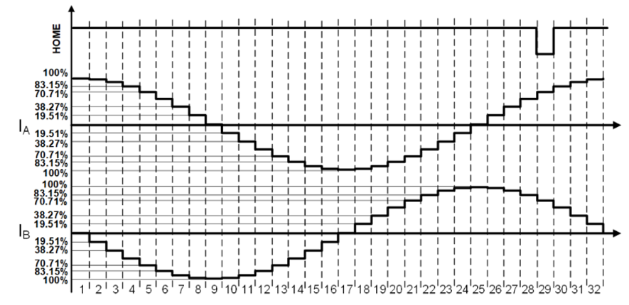
图 2:八步微步进模式下的 A 相和 B 相电流波形
带衰减模式的电流调节
慢速衰减和快速衰减是用来稳定每一步阶跃电流的典型控制方法。以 A 相上的单个阶跃为例,其电流调节波形如图 3 所示。电流调节功能通过控制四个 MOSFET 的导通/关断来实现,这四个 MOSFET由 A 相的全桥驱动器驱动。
下面将详细讨论这两种衰减模式。
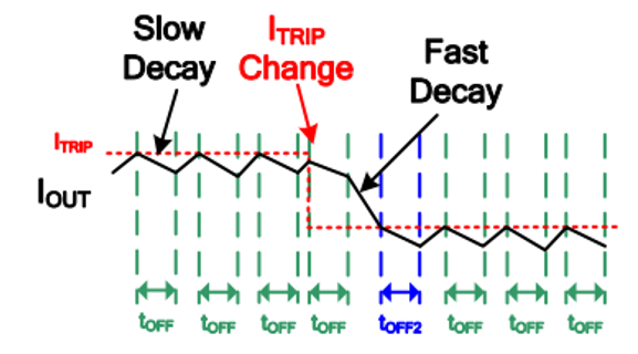
图3:A 相的电流调节波形
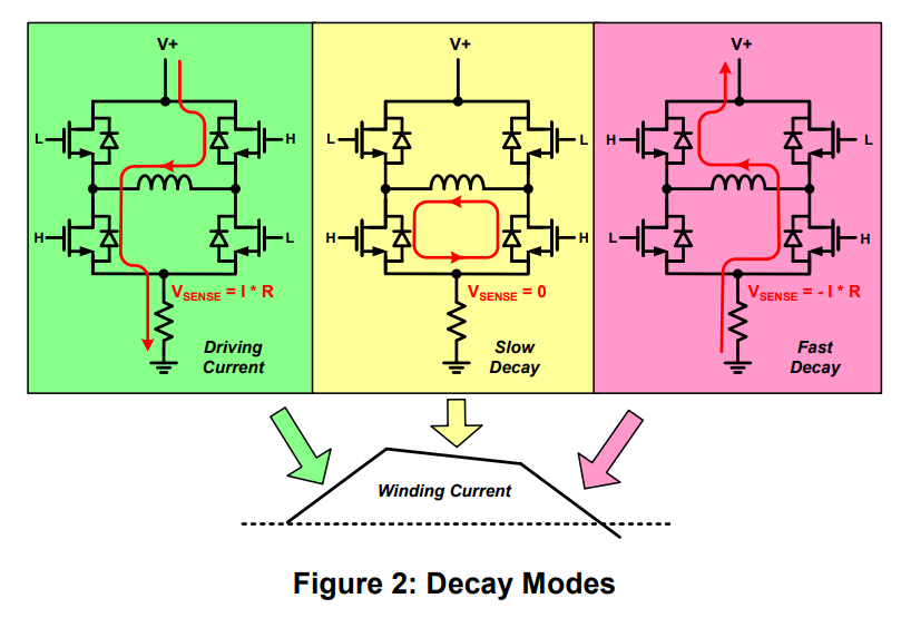
慢速衰减
当 Q1 和 Q4 导通时,电源电压 (U) 被施加到 A 相绕组上,电流开始上升。在相应等效电路中,R为绕组电阻,L为电感(具有等效阻抗),E为转子运动磁场在绕组中产生的反电动势EMF(见图4)。反向电动势作用在绕组电路上。
一旦电流达到所需值,就必须降低电流;否则,电流可能会持续增加并超过其设定值。此时,电流需要慢速衰减。
图4 显示了 A 相全桥驱动的慢速衰减过程。
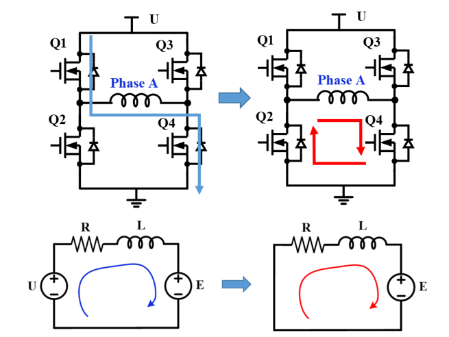
图 4:A 相全桥驱动的慢速衰减过程
关断 Q1 并导通 Q2(忽略死区时间)将进入慢速衰减。 它相当于将A相绕组短路。由于电流通过绕组电感,电流方向不会突然改变,而且电流在低侧的两个MOSFET中形成环流。此时只有反电动势(E)作用于电路,电流受反向压降(-E)的影响开始下降。如果忽略电阻引起的压降,电流将以E/L的速度减小。
电流下降一段时间之后,Q2 关断,Q1 导通,电流得以再次上升。这个过程稳定了每一步阶跃的电流。
快速衰减
当电流即将进入需要较低电流的阶跃时,电流需要进一步下降。如果电流下降得不够快,则慢速衰减的速度可能不足以将电流降低到所需的水平。此时就需要快速衰减(见图 5)。
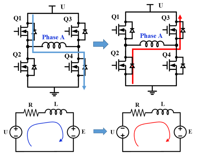
图5: A相全桥驱动的快速衰减过程
在快速衰减期间, Q2 和 Q3 在Q1 和 Q4 关断(忽略死区时间)之后导通。此时,电源电压反向施加在 A 相绕组上并与反电动势 (E) 串联。电流从Q2流向Q3,因为流经绕组电感的电流不会突然变化。电流以(E + U) / L的速度下降,下降速度比慢速衰减要快。
不同电流控制的比较
当电流下降到下一个阶跃的设定值时,电流调节方案可以从快速衰减变为慢速衰减。组合使用慢速衰减和快速衰减可以控制电流快速变化,与此同时还能最大限度地减少电流纹波。图 6 显示了快速衰减、慢速衰减以及组合模式下的电流波形(电流波形显示为绿色)。
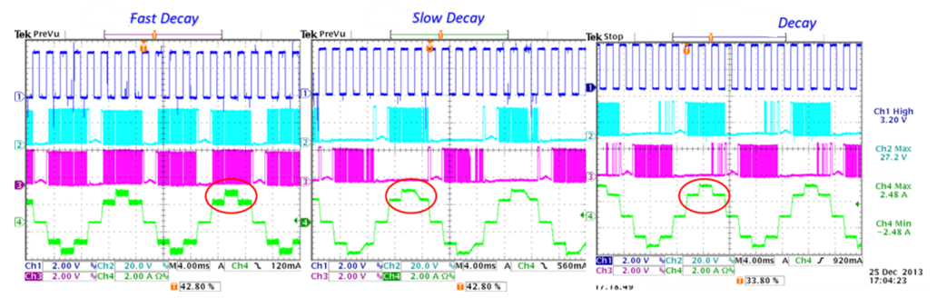
图 6:不同电流控制模式下的电流波形
在慢速衰减期间,电流在下降到下一个阶跃之前会在较长的时间内一直下降,这会导致波形失真。
在快速衰减和慢速衰减组合模式下,慢速衰减在双极性步进电机保持在一个阶跃位置时调节电流,而快速衰减则在电流必须快速下降到下一个阶跃值时更有效地控制电流。
结语
与整步或半步模式相比,微步进模式可以实现更精细的定位和更平滑的操作。本文讨论了如何在阶跃之间利用慢速衰减和快速衰减来稳定电流。此外,组合衰减模式还可以减少扭矩脉动,从而减少振动和噪音。
MPS 提供种类繁多的步进电机驱动器,可以满足各种应用需求。
_______________________
您感兴趣吗?点击订阅,我们将每月为您发送最具价值的资讯!
技术论坛
 Latest activity 3 months ago
 9 回复
Latest activity 3 months ago
50 回复
Latest activity 4 months ago
13 回复
9 回复
Latest activity 3 months ago
50 回复
Latest activity 4 months ago
13 回复
直接登录
创建新帐号