AN152 - 使用 MPQ6610 驱动螺线管

摘要
MARCH, 2018 - 螺线管的应用很广泛,它通常用于为机械系统提供线性或旋转驱动。驱动螺线管可以简单如接通和断开电流,但要获得良好的性能,则需要采用专用 IC 来驱动。
本应用笔记讨论了如何利用 MPSMPQ6610半桥驱动器 IC 来驱动螺线管,该IC采用电流控制来优化驱动与节能特性。
螺线管基础知识
最简单的螺线管就是一个能够产生磁场的线圈。但我们通常所称的“螺线管”器件则是包含了一个线圈和一个移动内芯的器件,其内芯可以是铁芯或其他磁性材料。将电流施加到线圈上可以导致内芯相对于线圈产生拉力或推力,从而产生运动以用于驱动机械系统中的某个物体。典型的螺线管如图 1所示。
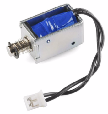
图1: 典型的螺线管
机电继电器的致动线圈也是螺线管。它们通常有一个固定铁芯或钢芯,磁场作用在一个可移动的部件上,该部件可合上继电器的电触点。
驱动螺线管时,需要将电压施加到线圈绕组上以产生磁场。绕组具有大电感,因此它需要一些时间来生成电流。螺线管铁芯上产生的力与电流成正比;因此,要产生移动铁芯的最大力,就需要施加高电压来快速生成电流。
可一旦运动完成,通常又需要一个小很多的电流来将铁芯保持在一个位置。此时如果继续施加全部电压,绕组会消耗大量能量,螺线管也会产生大量热量。
通常情况下,采用恒流驱动器来驱动螺线管可以解决这些问题。其电流可随时间控制,因此可提供理想的驱动力,同时还可以限制将螺线管保持在位所消耗的功率。
MPQ6610
MPS的MPQ6610 是一款具有电流测量与调节功能的半H桥驱动器。它支持高达 60V 的工作电压和 3A 负载电流,采用小尺寸 8 引脚 SOIC 或 TSOT23 封装。MPQ6610 的功能框图如图 1所示。
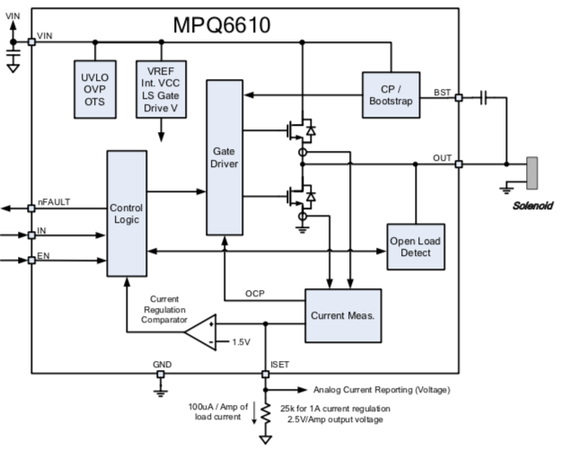
图1: MPQ6610功能框图
MPQ6610 可以调节任意方向的输出电流;也就是说,螺线管的另一端也可以接地或接至电源。其电流的调节通过内部测量输出级中的电流来实现;由于无需外部分流电阻器,因此相比其他解决方案节省了成本和 PCB 面积。调节电流由连接到 ISET 引脚上的小型外部编程电阻设置。
MPQ6610 还具备电流测量能力,该功能通过监测 ISET 引脚上的电压来实现。该器件利用微控制器中的 A/D 转换器来测量ISET 引脚电压,从而诊断确认螺线管中流动的电流。MPQ6610 还提供短路保护,并可通过 nFAULT 输出实现负载开路检测。
请参阅 MPQ6610 数据手册了解上述功能的详细信息。
控制螺线管保持电流
在螺线管最简单的实现中,通过连接到 ISET 引脚的单个电阻器可设置一个恒定的电流以驱动螺线管。首次启用时,其输出将保持激活,电流通过螺线管电感积聚,直至达到调节设定点。然后,MPQ6610 采用脉宽调制调节输出,交替高低电平,将电流调节至所需值。这通常已可以满足很多应用的需求。
但为了进一步提高能效,有些应用要求提供一个初始大电流以吸合螺线管,然后再将电流降低到足以将螺线管固定到位的水平。这样既能节省能量还可以减少螺线管中产生的热量。
在基本的 MPQ6610 应用电路中添加一些额外的组件就可以实现这一点,如图 2所示。
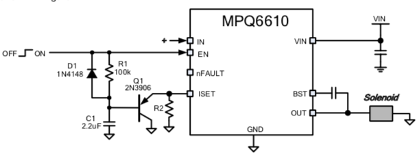
图 2 – MPQ6610 降低保持电流的电路
该电路的工作原理如下所述:
初始输入信号为低电平。通过 D1 对 C1 进行放电,并通过 Q1 将 ISET 引脚保持在低电平。
输入信号拉高,这启动了 MPQ6610同时拉高了输出,全电源电压施加在螺线管上。C1 开始通过 R1 充电。来自 ISET 引脚的电流与螺线管中流动的电流成正比;随着 C1被充电,ISET 引脚上的电压也逐步上升。
如果螺线管中有足够的电流流动,ISET 引脚上的电压就将持续上升,直至达到 1.5V 的电流调节阈值。然后,MPQ6610开始调节螺线管中的电流。
图 3展示了驱动电流波形。其中黄色迹线代表驱动螺线管的OUT信号,绿色迹线代表螺线管电流(由电流探头测得)。可以看到,最初的全电源电压被驱动以吸合螺线管,经过一段延迟时间(由上述电路中的 C1 和 R1 设置)之后,通过脉宽调制输出,电流减少到由 ISET 引脚电阻设置的水平。

图3: 降低的保持电流波形
延迟时间是 C1 通过 R1 充电至 1.5V减去 Q1 VBE(约 为900mV)的时间。该时间还取决于控制输入的逻辑高电压。对标准3.3V 逻辑电平而言,该延迟时间约为 0.33 x RC。对于上述 R=100k&Omega 且 C=2.2μF 的示例,延迟时间 0.33 x RC = 75mS。逻辑电压越高,延迟时间越短;逻辑电压越低,延迟时间越长。
调节后的保持电流由 R2 值设定。由于每 1A 负载电流的ISET 引脚电流为 100&mu,而调节阈值为 1.5V,所以电阻值为 R = 15 / I(其中 R 的单位为k&Omega,I的单位为A)。
控制螺线管吸合电流和保持电流
添加一个额外的电阻就可以实现最大吸合电流和保持电流的独立控制。在这种配置下,可以采用更高的电源电压以加速螺线管中的初始电流爬升,从而带来更优秀的机械性能(如图 4 所示)。
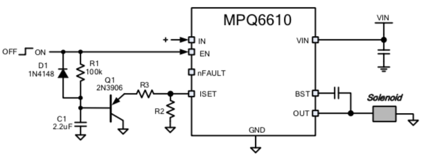
图 4:调节吸合电流和保持电流
如上所述,保持电流由 R2 设置。如果再添加一个 R3,则可在操作的吸合阶段提供电流限制。当 C1 初始放电时,电流由 R2 和 R3 的并联组合设定。随着 C1 被充电,电流会慢慢减小,直至达到 R2 设置的保持电流。
MPQ6610 螺线管驱动器评估板
MPS 提供前文所示电路的评估板,以供用户评估这个驱动其螺线管的电路。评估板原理图(见图5)和 PCB 布局(见图6)如下所示。

图 5 :螺线管评估板示意图

图 6 :螺线管评估板PCB布局
该评估板支持 5V 至 60V 的电源电压。使用时,将电源输入连接至 P1,螺线管连接至P3。“OUT”引脚将被驱动至 VIN 以启动螺线管。
如果使用内部滑动开关启用和禁用螺线管,则将跳线 JP1 留在原位。PCB 上还有一个小型 3.3V LDO 稳压器,用于提供启用 MPQ6610 的逻辑电平。如果要使用外部逻辑信号来控制电路,则移除 JP1 并将控制信号施加到 P2。控制信号可以是从 2.5V 到 5V 的任意逻辑电平;但要注意,该电压会影响延迟时间。
该板采用两个电位器用于控制吸合电流和保持电流。与 RV2 并联的 RV1 用于设置最大吸合电流,RV2 则用于设置保持电流。保持电流将始终小于吸合电流。如果将吸合电流一直调高,则吸合电流不会受到限制。在 最小RV2 设置下,保持电流将被限制在大约 300mA。
MPQ6610 还提供过流保护电路;电流达到 3A 至 6A 之间时,保护功能将激活。如果螺线管所耗电流超过此范围,MPQ6610将禁用输出 1mS,然后再重新启用。
直接登录
创建新帐号