Circuit analysis, electromagnetics, and control theory are integral to the theoretical framework of a Half-bridge topology. Comprehending these theoretical foundations is essential for designing and analyzing the circuit's behavior. Below are the fundamental theoretical aspects of a Half-bridge converter:
Switching States and Operation: At the core of a Half-bridge converter's operation is its capacity to alternate between two distinct switching states: The upper switch (Q1) is turned ON while the lower switch (Q2) is turned OFF, and vice versa. The average output voltage and power flow regulation are determined by the modulation of these switching states.
Duty Cycle and Output Voltage: The output voltage is directly influenced by the duty cycle, which is represented by the ratio of the time each switch is ON to the total switching period. Nonetheless, the effective duty cycle is twice that of the individual duty cycle of the switches.
$$D_{per\_switch} = \frac{V_{out}}{V_{in}} \cdot \frac{N_p}{N_s}$$Here, Vout represents the output voltage, Vin denotes the input voltage, Np signifies the number of turns on the primary side of the transformer, and Ns indicates the number of turns on the secondary side of the transformer. As a result, the effective frequency is doubled compared to the individual switch frequencies. A small transformer, as well as reduced input and output filtering requirements, are facilitated by this significant advantage.
Voltage and Current Waveforms: Analyzing the voltage and current waveforms across the switches, load, and other components is integral to theoretical analysis. Understanding different phases, the shapes of the associated waveforms, and the transition periods between switching states are part of this analysis.
Energy Storage and Transfer: Playing a critical role, the DC bus capacitor stores and transfers energy throughout the switching cycles, thereby smoothing voltage variations and maintaining a consistent, stable energy supply to the load. Considering the energy transfer mechanisms and ensuring proper sizing of the capacitor for the desired performance are part of theoretical analysis.
Control Strategies: Control strategies used in the modulation of switching states are part of theoretical analysis. A widely used technique, pulse width modulation (PWM) adjusts the duty cycle according to the desired output voltage or power regulation, guided by its theoretical principles.
Efficiency and Power Losses: Theoretical foundations also cover the efficiency of the Half-bridge converter. Examining power losses, which include switching losses, conduction losses in switches, and losses in magnetic components, aids in optimizing the efficiency of the converter.
Exploring these theoretical aspects enables engineers to craft, refine, and troubleshoot Half-bridge converters across diverse applications, guaranteeing dependable and effective functionality in practical situations.
How Changes in Components Affect Behavior
Inductor (L): Boosting inductance decreases ripple current but might augment the physical dimensions of the inductor. Elevated ripple currents and amplified power losses can occur due to reduced inductance values.
Capacitor (C): Output voltage stability is influenced by the DC bus capacitor. Increased capacitance values decrease the output voltage ripple. Nevertheless, higher expenses and slower voltage response can be caused by excessive capacitance.
Switching Frequency (fsw): Increasing switching frequencies results in smaller passive component sizes, such as inductors and capacitors, while simultaneously elevating switching losses. Larger passive components are necessary as switching frequencies are reduced, which in turn diminish switching losses.
Duty Cycle (D): To adjust the output voltage, changing the duty cycle is necessary. A higher output voltage is achieved with higher duty cycles. Efficiency and control challenges may be impacted by extremely high or low duty cycles.
Feedback Control: Voltage regulation can be enhanced by implementing feedback control systems, which compensate for fluctuations in load and input voltage. It's essential to comprehend the mathematical relationships and the influence of feedback control.
Feedback Topology for Half-Bridge Converter
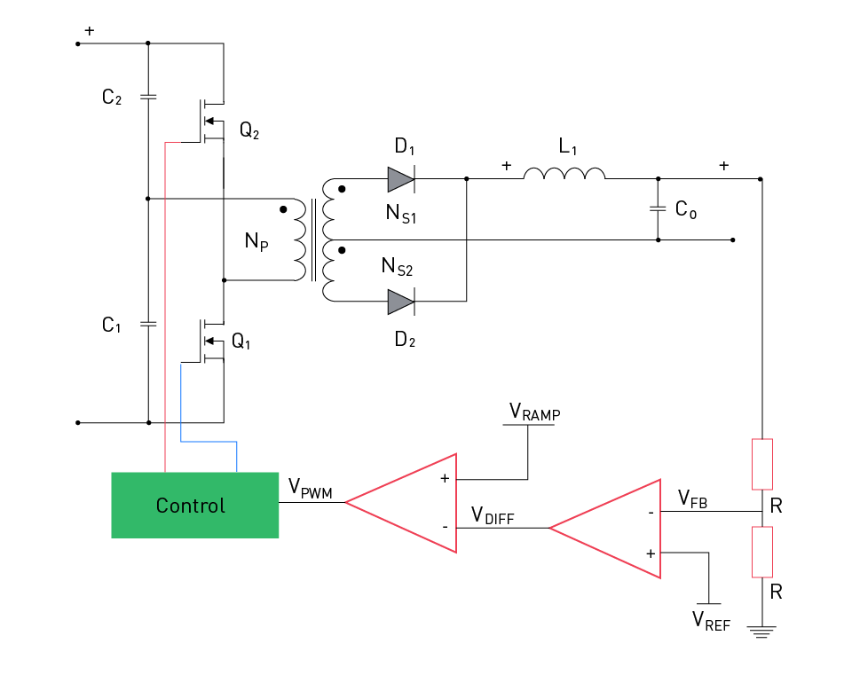
Figure 15: Half-Bridge Converter Feedback Topology
The figure above illustrates a feedback topology for the half-bridge converter. The most common and widely utilized feedback technique is the voltage divider feedback. The output of this divider, denoted as VFB, is compared with a reference voltage Vref (set voltage), that can be internal or external to the controller. Comparing the error voltage Vdiff with the ramp voltage Vramp (ramp voltage of a fixed frequency) results in a PWM with a duty cycle proportional to the output voltage. To prevent both gates from turning on simultaneously, a control block is evident here. The operation of feedback heavily relies on the critical values of these feedback resistors. Knowing the reference voltage is essential for setting Vout along with understanding the feedback resistors' values.
$$V_{out} = V_{ref} \left( \frac{R_{FBT} + R_{FBB}}{R_{FBB}} \right)$$The values of feedback resistance can be found from this equation once the Vout (designed output voltage) is known.
$$R_{FBT} = R_{FBB} \left( \frac{V_{out}}{V_{ref}} - 1 \right)$$RFBT can be calculated and RFBB may be selected between 20-200 kΩ . It's worth considering that elevated values of these resistances may compromise the stability of the op-amp, whereas lower values could lead to excessive current draw, consequently reducing efficiency.
Considerations and Design Tradeoffs
Sensitivity to Component Variations: Variations in components, like changes in load or temperature, are influenced by the sensitivity of the control loop to variations, which is determined by the feedback resistor's value. Balancing sensitivity and stability require careful consideration.
Power Dissipation: In the overall power budget of the system, the power dissipated across the feedback resistor should be considered to decrease the no-load power consumption. Increased power dissipation may result from higher resistor values.
Bandwidth and Response Time: The bandwidth and response time of the control loop are influenced by the choice of feedback resistor. For a swift and steady system response, engineers must factor these conditions.
In summary, the feedback resistance in Half-bridge converters is a critical component in the voltage regulation loop. It allows engineers to fine-tune the output voltage and ensures that the converter responds effectively to changes in operating conditions. Proper design and consideration of the feedback network contribute to the overall performance and stability of the Half-bridge converter.
直接登录
创建新帐号