AN236 - MPS 电量计工作原理

每月为您发送最具参考价值的行业文章
我们会保障您的隐私
简介
本文将介绍 MPS 电量计(Fuel Gauge,FG)的工作原理及正确配置方法,包括 MPS 标准型电量计(Standard Fuel Gauge,SFG) 和 MPS 控制器型电量计(Controller Fuel Gauge,CFG)。虽然这两类电量计采用相同的电量计算法,但支持的系统架构不同,且采用了不同的状态机实现方式。其中,SFG通过中间微控制器单元(MCU)进行控制;MCU 通过电池监控与保护器件(模拟前端,AFE)获取电池测量数据,并将数据写入 SFG(见图1)。CFG 则直接控制 MPS AFE,无需中间 MCU(见图2)。本文中凡提及发送至 CFG 的命令,同样适用于 CFG 与 AFE 器件之间的通信命令。
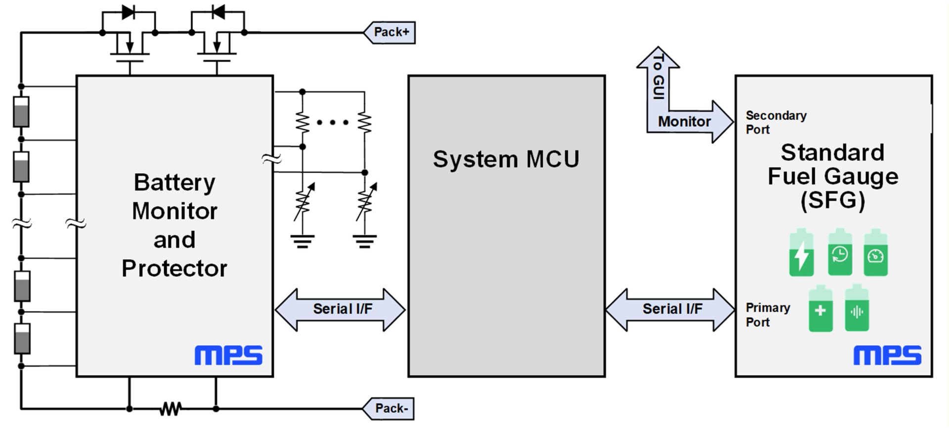
图1:基于 MPS 标准型电量计(SFG)的 BMS 架构
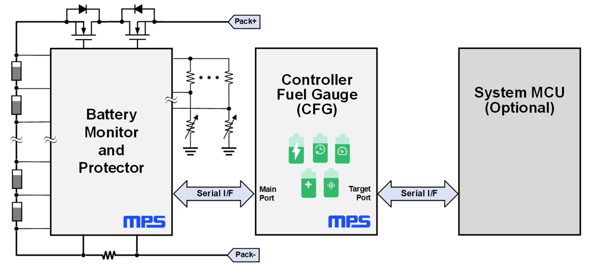
图2:基于 MPS 控制器型电量计(CFG)的 BMS 架构
文中提及的Initiator(发起端) 和 Target(目标端) 用于表述I2C接口的两种类型。SFG 集成了一个 Target I2C 接口,该接口由 MCU 上的 Initiator I2C控制;CFG 则集成了 Initiator I2C 接口,可直接控制 AFE 的 Target I2C 接口。
电量计和控制器型电量计工作
标准型电量计(SFG)工作模式
图3所示为 SFG 的电源状态图。有关电源状态切换流程的详细说明,请参阅“通信”章节。
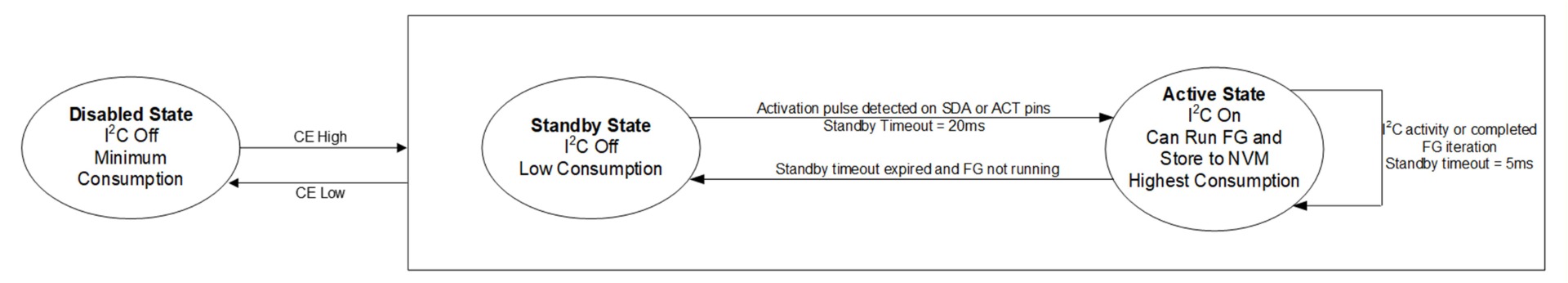
图3: SFG电源状态图
控制器型电量计(CFG)工作模式
图4所示为 MPF42780 的 CFG 状态图。CFG 共支持 10 种工作模式,通过 BMS_STATUS 寄存器可读取当前工作模式。
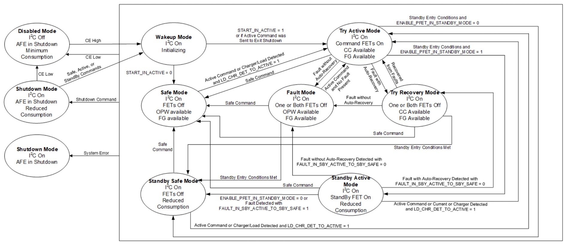
图4:MPF42780 状态图
图5所示为 MPF42781 的 CFG 状态图。
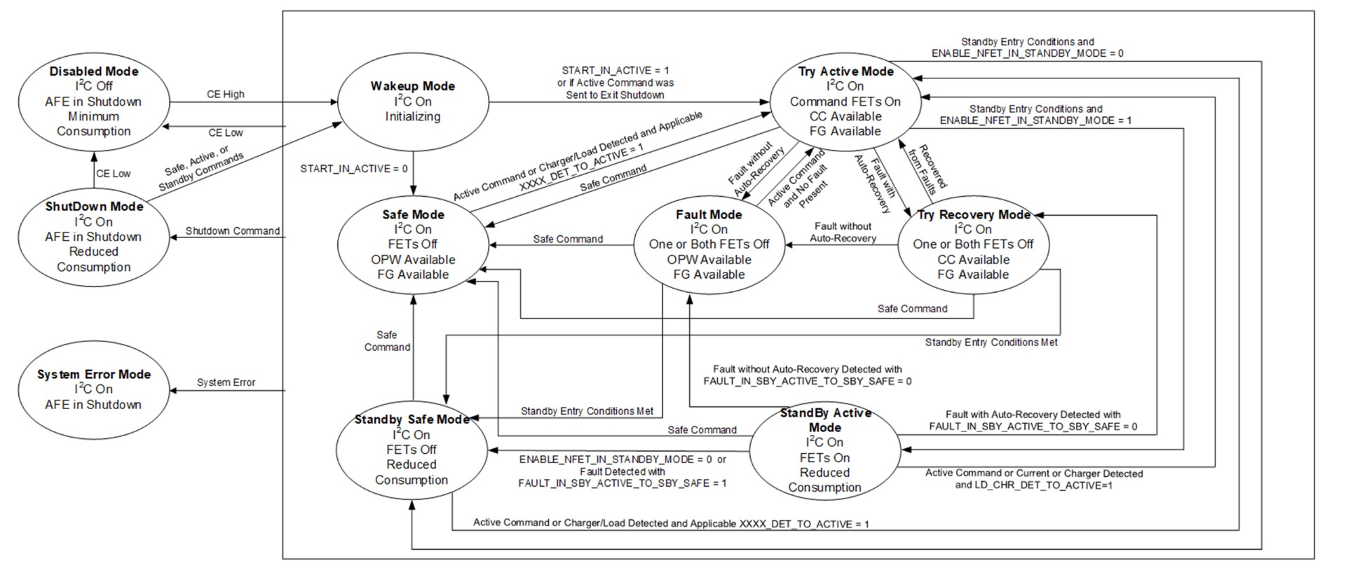
图5:MPF42781 状态图
下面将分别介绍各工作模式。有关相关寄存器的详细说明,请参阅器件数据手册。
Wake Up(唤醒模式)
Wake Up(唤醒)模式是在器件初始化完成之前的临时状态。在该状态下,保护 MOSFET 保持断开。START_IN_ACTIVE 寄存器用于定义初始化完成后的目标状态。如果初始化结束时 START_IN_ACTIVE = 0,则器件进入 Safe(安全)模式;如果初始化结束时 START_IN_ACTIVE = 1,则 CFG 尝试进入 Try Active(尝试激活)模式。
相关寄存器:
- BMS_STATUS
- START_IN_ACTIVE
Safe(安全模式)
在 Safe(安全)模式下,CFG 命令电池监控器保持保护 MOSFET 断开,从而使电池保持安全状态。可向 CFG 发送 SAFE_MODE_CMD 命令进入 Safe 模式。如果上一状态为 Try Recovery(尝试恢复)模式 或 Fault(故障)模式,则 CFG 会在切换至 Safe 模式的过程中尝试清除故障。在 Safe 模式下,可通过 ENABLE_SCOC_SAFE 寄存器来使能短路(SC)和过流(OC)监测,此外还可读取 SAFE 位以确认 MP279x 是否处于 Safe (安全)状态。
相关寄存器:
- BMS_STATUS
- START_IN_ACTIVE
- SAFE
- SAFE_FLAG
- ENABLE_SCOC_SAFE
Try Active(尝试激活模式)
在 Try Active(尝试激活)模式下,当不存在故障时,CFG 会尝试闭合 AFE 的保护 MOSFET。即使上一状态为 Fault(故障)模式,也可以向 CFG 发送 ACTIVE_MODE_CMD 命令尝试进入 Try Active 模式;CFG 将首先尝试清除故障,然后进入 Try Active 模式。在该模式下,器件可读取 ACTIVE 位以确认 AFE 是否处于 Active/Normal B 状态。
相关寄存器:
- BMS_STATUS
- ACTIVE_MODE_CMD
- ACTIVE
- ACTIVE_FLAG
Try Recovery(尝试恢复模式)
当 CFG 或 AFE 检测到一个或多个故障,并且所有当前故障均启用了自动恢复功能时,系统进入 Try Recovery(尝试恢复)模式。在此模式下,相应的保护 MOSFET 保持断开,直至故障被清除,随后器件自动尝试进入 Try Active 模式。
相关寄存器:
- BMS_STATUS
- BMS_ALARMS
- BMS_RT_ALARMS
- FAULTS_EN
- FAULTS_REC_EN
- FAULTS_1FET_EN(MPF42780)
- FAULTS_2FET_EN(MPF42781)
Fault(故障模式)
当 CFG 或 AFE 检测到一个或多个未启用自动恢复的故障时,系统进入 Fault(故障)模式。此时,相应的保护 MOSFET 保持断开。必须手动清除故障后,才能退出该模式。在此模式下,可读取 FAULT 位以确认 AFE 是否处于 Fault/Normal C 状态。
相关寄存器:
- BMS_STATUS
- FAULT
- BMS_ALARMS
- BMS_RT_ALARMS
- FAULTS_EN
- FAULTS_REC_EN
- FAULTS_1FET_EN(MPF42780)
- FAULTS_2FET_EN(MPF42781)
Standby Safe(安全待机模式)
Standby Safe(安全待机)模式与 Safe (安全)模式类似,但功耗更低。在该模式下,电量计算法停止运行; AFE 的高分辨率(HR)扫描仅每 3 s 执行一次; 当没有需要处理的任务时,CFG 自动切换至 Sleep(休眠)省电状态。 CFG 可通过以下两种方式进入 Standby Safe 模式:接收 STANDBY_MODE_CMD 命令; 或满足自动进入安全待机模式的条件。
相关寄存器:
- BMS_STATUS
- STANDBY_MODE_CMD
- ENABLE_AUTOSBY
- TIME_TO_STANDBY
- STANDBY_CURRENT_THRESHOLD
- AUTOSBY_FROM_ACTIVE
- ENABLE_PFET_IN_STANDBY_MODE(MPF42780)
- ENABLE_NFET_IN_STANDBY_MODE(MPF42781)
- FAULT_IN_SBY_ACTIVE_TO_SBY_SAFE
- AUTOSBY_FROM_FAULT
- AUTOSBY_FROM_RECOVERY
Standby Active(激活待机模式)
对于 MPF42780,Standby Active(激活待机)模式与 Standby Safe (安全待机)模式的区别在于:AFE 的保护 MOSFET 保持断开; Standby Discharge(SBYDSG)MOSFET 保持导通。 对于 MPF42781,Standby Active 模式与 Standby Safe 模式的区别在于:保护 MOSFET 保持导通。 如果 AFE 检测到电流超出待机范围,或 MPF42780 检测到充电器接入,则器件会自动退出该模式,并返回 Try Active 模式。
仅当满足以下条件时,才能从 Try Active 模式进入 Standby Active 模式:ENABLE_NFET_IN_STANDBY_MODE = 1; 接收到 STANDBY_MODE_CMD 命令,或满足自动进入待机模式的条件。
相关寄存器:
- BMS_STATUS
- STANDBY_MODE_CMD
- ENABLE_AUTOSBY
- TIME_TO_STANDBY
- STANDBY_CURRENT_THRESHOLD
- AUTOSBY_FROM_ACTIVE
- ENABLE_PFET_IN_STANDBY_MODE(MPF42780)
- ENABLE_NFET_IN_STANDBY_MODE(MPF42781)
- FAULT_IN_SBY_ACTIVE_TO_SBY_SAFE
Shutdown(关断模式)
在 Shutdown(关断)模式下,AFE 被命令进入关断状态,CFG 则切换至 Sleep(休眠)状态。在该模式下:保护 MOSFET 保持断开; 电量计功能被禁用; 不再监测电池参数。 CFG 的 Target I²C 接口在 Shutdown 模式下仍然可用,可用于切换至其他工作模式。
相关寄存器:
- BMS_STATUS
- SHUTDOWN_MODE_CMD
- SHUTDOWN_FLAG
Disabled(禁用模式)
Disabled(禁用)模式与 Shutdown 模式类似。在该模式下:AFE 被命令进入关断状态; 保护 MOSFET 保持断开; 电量计功能被禁用; 不监测电池参数。 不同之处在于:Target I2C接口不可用; CFG 被完全禁用。 将 CE 引脚拉低即可进入 Disabled 模式。
该模式没有对应的I2C寄存器。
System Error(系统错误模式)
System Error(系统错误)模式仅在以下情况下进入:CFG 与 AFE 通信丢失; 系统发生其他异常行为。 退出该模式只能通过复位实现,包括:切换 nRST 引脚; 电源重新上电; 或发送 IC_RST_CMD 命令。 此外,在 System Error 模式下,发送SAFE_MODE_CMD 或 ACTIVE_MODE_CMD 命令同样会触发系统复位。
相关寄存器:
- BMS_STATUS
- SYSTEM_ERROR_RT
- SYSTEM_ERROR
- IC_RST_CMD
- SAFE_MODE_CMD
- ACTIVE_MODE_CMD
控制器型电量计(CFG)电源状态
在运行过程中,MPS CFG会根据当前任务在不同电源状态之间切换(见图6)。为了尽可能降低电池电流消耗,CFG 会在条件允许时自动切换至功耗最低的电源状态。
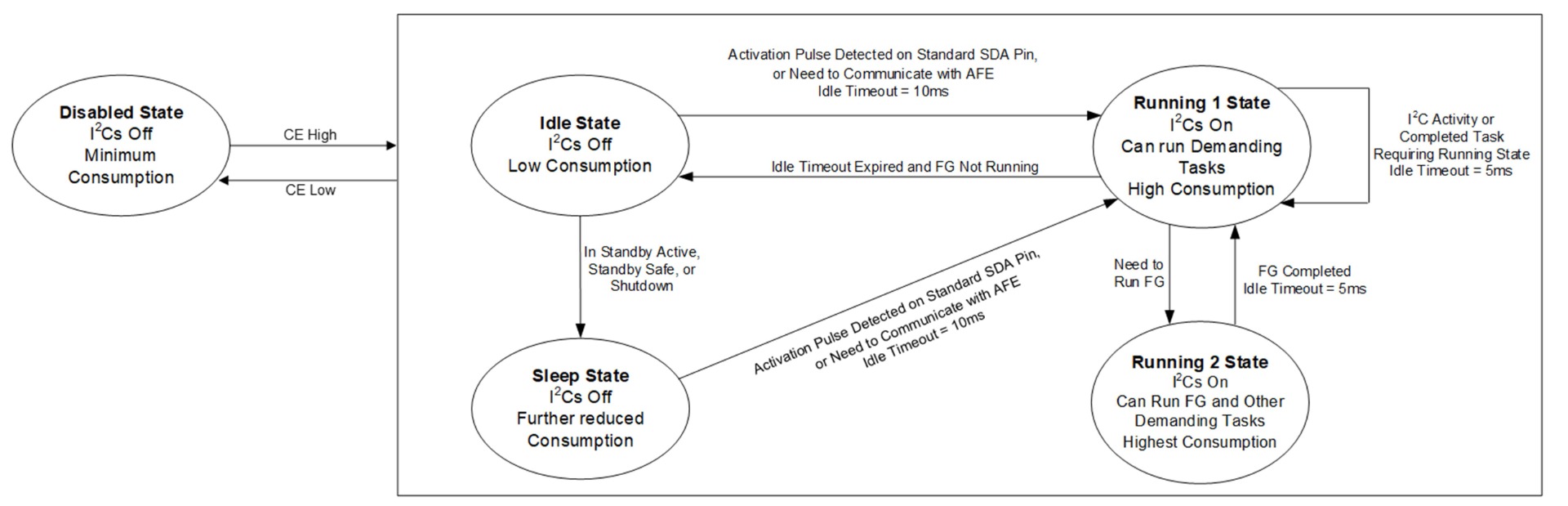
图6:MPF42780/MPF42781 电源状态图
以下介绍各电源状态。
运行状态
当 CFG 需要执行高负载任务时,会切换至某一种运行状态,以成功完成这些任务。
运行 2 状态可实现最高的内部计算速度,用于初始化过程、将电量计配置存储至非易失性存储器(NVM),以及运行电量计算法。
运行 1 状态具备足够的处理能力,可通过 I2C端口完成通信。当不需要运行 2 状态,但需要与 AFE 或目标I2C接口进行通信时,将使用该状态。
空闲状态
为了在不需要执行高负载任务时降低电流消耗,MPF42781 会切换至空闲状态。与运行状态相比,该状态具有更低的电流消耗。
睡眠状态
当处于关机状态或任意待机模式时,睡眠状态优先于空闲状态,以进一步降低电流消耗。
禁用状态
当 CE 为低电平时,CFG 处于禁用状态,以实现最低可能的电流消耗。
通信
目标端地址设置
默认目标端地址为 0x08。写入该寄存器后立即生效,因此用户必须在后续 I²C 通信中使用新的目标端地址。I2C_ADDRESS 寄存器保存器件的 7 位 Target I²C地址;在地址帧中,该地址左移 1 位,以便为读/写(R/W)位预留位置。因此,当默认值为 0x08 时,地址帧应为 0x10(写)或 0x11(读)。
相关寄存器为 I2C_ADDRESS。
进入 Active/Running 电源状态
若要强制器件从 Standby/Idle/Sleep 状态切换至 Active/Running 状态,需要在 SDA 或 ACTx 引脚上施加一个持续至少 1ms 的低电平脉冲。因此,进入 Active/Running 状态需要先发送一个起始条件,并在 1ms 后发送一个停止条件。需要注意的是,从低电平脉冲开始起约需 6ms,电量计才能完全进入 Active/Running 状态,并使 I2C接口准备就绪。
CFG 进入 Running 状态后,必须在 10ms 的时间窗口内开始通信。对于进入 Active 状态的 SFG,该时间窗口为 20ms。否则,电量计将超时,并重新切换回 Standby/Idle/Sleep 状态。操作完成后(例如与用户进行I2C通信、与 AFE 通信或完成一次电量计迭代),IC 会在等待 5ms 后重新进入 Standby/Idle/Sleep 状态。
时钟拉伸
Target I2C 在执行其他任务时无法完成一个完整字节的数据收发,但它可以在第 9 个时钟脉冲之后将 SCL 保持为低电平,使Initiator I2C 进入等待状态(Clock Stretching,时钟拉伸)。当 Target I2C 准备就绪后,数据传输继续进行,同时释放时钟线(SCL)(见图7)。
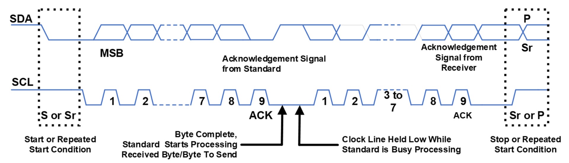
图7:I2C 时钟拉伸
协议层
电量计通信协议用 2 个字节表示寄存器地址和命令地址。同时包含一个长度字段,用于声明每次读写事务中的数据字节数。除非器件数据手册另有说明,否则单次事务允许的最大数据长度为 82 字节(不包括寄存器地址、长度字节及循环冗余校验(CRC)字节)。
循环冗余校验(CRC)
CRC 用于保证通信事务的完整性。启用 CRC 后,事务的最后 4 个字节为 CRC 校验值。CRC 的计算范围包括寄存器地址、长度字段以及数据载荷,并以每 4 个字节为一组进行计算。如果数据字节数不是 4 的整数倍,则使用 0x00 对最后一组进行填充。
I2C_CRC_EN 位用于决定 I²C 通信是否启用 CRC。如果禁用 CRC,则写事务无需包含 CRC 字节即可被接受,无论 CRC 字节是否存在或是否正确,写事务都会被接受。在读事务中,FG 不会返回 CRC,因此Initiator I²C会在最后一个数据字节之后发送非应答(NACK)信号和停止命令。
所采用的 CRC 算法为 CRC-32/MPEG-2,其生成多项式为 CRC-32(1 + x1 + x2 + x4 + x5 + x7 + x8 + x10 + x11 + x12 + x16 + x22 + x23 + x26 + x32),初始值为 0xFFFFFFFF,不进行位反转,也不进行最终 XOR 运算。
下面给出了基于 C 语言实现的 CRC 计算算法。
unsigned long crc32 (unsigned short Reg_Address, unsigned char length, unsigned char *data){
  short i;
  unsigned long crc = 0xffffffff;
  unsigned char dataTemp[4];
  for (i=-1; i < len; i++){
    if (i==-1) {
      dataTemp[0]=len;
      dataTemp[1]=Reg_Address & 0x00FF;
      dataTemp[2]=(Reg_Address & 0xFF00) >> 8;
      dataTemp[3]=0;
    }
    else dataTemp[i%4]=data[i];
    if((i%4)==3 || i == len-1 || i==-1) {
      for (char j=0; j < 4; j++) {
        crc ^= dataTemp[3-j] << 24;
        for (char k=0; k < 8; ++k) {
          if ((crc & 0x80000000) != 0)
            crc = (crc << 1) ^ 0x04C11DB7;
          else
            crc <<= 1;
        }
      }
      dataTemp[0]=0;
      dataTemp[1]=0;
      dataTemp[2]=0;
      dataTemp[3]=0;
    }
  }
  return crc;
}
相关寄存器为 I2C_CRC_EN。
I2写事务
MPS 电量计的 I2C 写事务包括:R/W 位为 0(写)的Target I2C 地址字节、2 个字节的 16 位寄存器地址、1 个表示待写入数据长度的数据长度字节、数据字节,以及4 个 CRC 字节(如果启用), 见图8。
向寄存器 0x10C3 写入 0x09C4(2 个字节:0xC4、0x09)的过程如下:
- Initiator I2C 将 SDA 拉低 1ms至6ms。
- 从低电平脉冲开始计时,等待>5ms 至 <13ms(CFG),或< 23ms(SFG)。
- Initiator I2C发送 Start 命令,随后发送Target I2C地址字节及写命令(当 I2C_ADDRESS=0x08 时为 0x10),并检查电量计是否返回 ACK(FG ACK),这表示电量计已经进入 Active/Running 状态。
- 写入寄存器地址(0x10C3),先发送 0xC3 并检查 FG ACK,再发送 0x10 并检查 FG ACK。从本步骤开始以及后续所有步骤中,相邻两个字节之间的发送间隔必须小于 5ms。
- 写入数据字节 0(bits[7:0],0xC4),并检查 FG ACK。
- 写入数据字节 1(bits[15:8],0x09),并检查 FG ACK。
- 如果未启用 CRC,则直接跳至步骤 13。如果启用了 CRC,则必须发送正确的 4 个 CRC 字节,本例计算得到 CRC = 0x5385D9AD。
- 写入 CRC Byte 0(bits[7:0],0xAD),并检查 FG ACK。
- 写入 CRC Byte 1(bits[15:8],0xD9),并检查 FG ACK。
- 写入 CRC Byte 2(bits[23:16],0x85),并检查 FG ACK。
- 写入 CRC Byte 3(bits[31:24],0x53),并检查 FG ACK。
- Initiator I2C可发送 Stop 命令结束本次传输,也可发送 Repeated Start 命令开始新的传输。
写入数据长度(0x02),并检查 FG ACK。
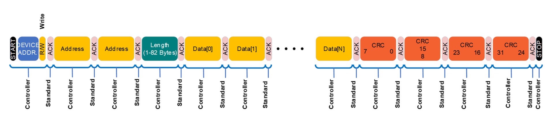
图8:带 CRC 的 I2C 写事务
I2C 读事务
MPS 电量计的 I2C 读事务包括:R/W 位为 0(写)的 Target I2C地址字节、2 个字节的 16 位寄存器地址、1 个表示要读取数据长度的数据长度字节、stop + start 或Repeated Start、R/W 位为 1(读)以开始读取的 第2个Target I2C地址字节、数据字节,以及4 个 CRC 字节(如果启用),见图9。
读取寄存器 0x12C0(4 个字节)的过程如下:
- Initiator I2C 将 SDA 拉低 1ms 至 6ms。
- 从低电平脉冲开始计时,等待时间应大于 5ms 且小于 13ms(对于 CFG),或小于 23ms(对于 SFG)。
- Initiator I2C 发送Start命令:Target I²C 地址字节 + 写操作(当 I2C_ADDRESS = 0x08 时为 0x10),并检查 FG 是否返回 ACK(这表示电量计处于 Active/Running 状态)。
- 写入寄存器地址(0x12C0):先写入 0xC0,并检查 FG 返回 ACK;然后写入 0x12,并检查 FG 返回 ACK。对于本步骤以及以下所有步骤,必须确保相邻两个字节之间的发送间隔小于 5ms。
- 发送Stop命令后再发送Start命令,或直接发送Repeated Start命令。随后发送 Target I2C 地址字节 + 读操作(当 I2C_ADDRESS = 0x08 时为 0x11),并检查 FG 返回 ACK。
- 读取 Byte 0,并返回 ACK。
- 读取 Byte 1,并返回 ACK。
- 读取 Byte 2,并返回 ACK。
- 读取 Byte 3。
- 如果禁用了 CRC,则跳转至步骤 16;如果启用了 CRC,则继续接收后续 4 个 CRC 字节。
- 读取 CRC Byte 0,并返回 ACK。
- 读取 CRC Byte 1,并返回 ACK。
- 读取 CRC Byte 2,并返回 ACK。
- 读取 CRC Byte 3。
- Initiator I2C 返回 NACK,随后可以发送Stop命令结束本次传输,或发送Repeated Start命令开始新的传输。
写入数据长度(0x04),并检查 FG 返回 ACK。
在本示例事务中,如果数据字节为 {0xF4, 0x01, 0x64, 0x00},则计算得到的 CRC 为 0x469B7F60。这意味着,为确保数据传输的完整性,CRC 字节应为 {0x60, 0x7F, 0x9B, 0x46}。
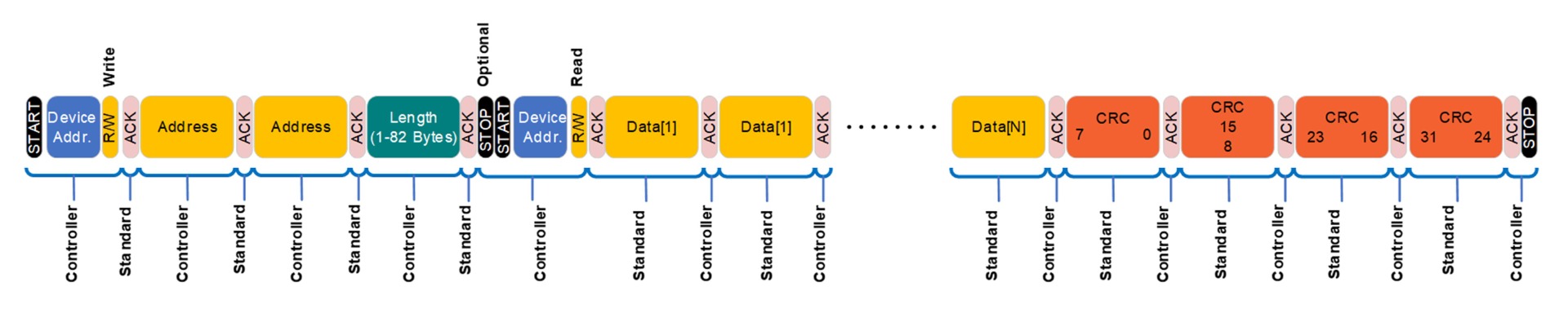
图9:带 CRC 的 I2C 读事务
电量计算法(SFG/CFG)
MPS 的电量计采用混合模型充电状态(SOC)算法来计算电芯/电池组的 SOC。与常见的开路电压(OCV)方法或库仑计数方法相比,MPS 电量计可在瞬态情况下提供准确的 SOC 结果,并且无需通过完整的充放电循环来更新满电容量。该电量计模型可降低库仑计数累积误差。对于某些无法达到完全充电或完全放电状态的特定应用,MPS 电量计无需校准即可获得优异的 SOC 结果。
本节内容主要介绍与 FG 算法相关的寄存器及其使用方法。读者将了解这些寄存器的定义及其工作方式,以在需要时更改默认值。
有某些寄存器仅在 GUI 的专家模式下显示。这部分内容可能与 CFG 或 SFG 均相关。
一次电量计迭代中的 SOC 计算过程如下:
- 获取读数。以下读数应从 AFE 获取。
- 电芯和电池组电压。如果无法提供电池组电压,则禁用电池组电压读取功能(VRDG_PACK_EN 位)。
- 电芯和电池组电流。如果无法提供电芯电流,则禁用电芯电流读取功能(IRDG_CELLS_EN 位)。
- 温度点。
- 库仑计数。如果无法提供库仑计数,则禁用库仑计数功能(CCRDG_EN 位)。
对于 SFG,用户必须在每次电量计迭代时将这些测量数据发送至电量计,以确保正确运行。对于 CFG,CFG 会每 500ms 触发一次高精度扫描,以获取电量计所需的所有测量数据,并完成电池监控。
- 当满足条件时,更新学习参数;
- 更新 SOC 状态;
- 更新健康状况(SOH)状态以及 SOH 学习;
- 更新电源状态;
- 检查可能存在的警告;
- 保存存储结果
- 结束迭代:
- 此时,电量计已准备好发送电量计输出结果;
- 如果启用该功能,电量计会将 IRQ 引脚拉低。
电芯模型选择
电量计算法必须使用可通过 MPS 图形用户界面(GUI)直接上传的电芯数学模型。用户可以直接从电芯数据库中选择,也可以通过 MPS 提供的文件加载电芯模型。用户可读取电芯模型信息,以确保已加载的是正确的电芯模型。
主要设置
执行周期(EXE_TIME 命令)定义电量计算法的执行频率。最小执行时间为 500ms,即电量计算法每 500ms 运行一次。发送至 FG 的测量数据获取频率必须严格遵循执行时间设置。
对于 SFG,用户应按照执行周期(EXE_TIME)配置的频率发送执行命令(EXE_CMD 命令)。对于 CFG,如果启用了电量计功能(FG_EN 命令),CFG 可以自动触发迭代。
在系统充电或放电时,FG 会在每次算法迭代中估算剩余空电时间/满电时间。当系统未处于充电或放电状态时,FG 会根据静置执行周期倍率(WEXE_TIME_REST 寄存器)降低空电/满电估算频率,以降低功耗;空电/满电估算会按照(EXE_TIME × WEXE_TIME_REST)的周期执行一次。
例如,如果 EXE_TIME = 4s 且 WEXE_TIME_REST = 4,则 FG 每 16s 执行一次满电/空电估算。
实际算法执行时间取决于所需的计算规格以及电量计 IC。通常配置为 10s 的 MPF42791,仅进行 SOC 估算时约需要 25ms,而执行满电/空电估算时约需要 400ms。当执行周期设置为 500ms 时,剩余约 100ms 可用于重新加载 AFE 数据,以进行下一次 FG 迭代。
充电/放电电流阈值(CHG_ITH 和 DSG_ITH 寄存器)用于判定电池正在充电或放电。当电流低于这些阈值时,FG 将电池视为静置状态。
最大 SOC 变化斜率(SOC_DMAX 寄存器)定义每秒充电/放电过程中 SOC 最大变化量。
例如,当以 1C 放电时,SOC 变化斜率约为 100% / 3600s = 0.028%/s。对于最高 1C 的应用,该设置应略高于 0.028%/s,以确保正常运行。当应用更高 C 倍率时,必须增大该设置,以确保电量计报告的 SOC 曲线能够跟随实际充放电曲线。
最大静置 SOC 变化斜率(SOC_DMAX_REST 寄存器)定义电池在当前电流水平静置状态下,每秒允许的最大 SOC 变化量。如果用户不希望 SOC 在静置状态下发生变化,则该值应设置为 0。
电池组配置
串联电芯数量(NCELLS_SER 寄存器)设置整个电池组中的串联电芯数量,并影响电池组电压。
并联电芯数量(NCELLS_PAR 寄存器)设置整个电池组中的并联电芯数量,并影响电池组容量。
温度传感器数量(NTSS 寄存器)设置电池组中使用的 NTC 总数量。当与 MPS AFE 匹配时,该数量应与电芯监控 NTC 数量(NUM_OF_CELL_NTCS 寄存器)的设置保持一致。
温度配置
电芯温度选择(TSS_CELLX 寄存器)定义每个电芯温度 NTC 与其所监测电芯之间的对应关系。
最大充电温度(TCHG_MAX 寄存器)根据客户应用设置充电过程中的最大温度。该参数用于预测充电过温警告(WARN_OTCHG_CC 寄存器和 WARN_OTCHG_END 寄存器)。
最大放电温度(TDIS_MAX 寄存器)根据客户应用设置放电过程中的最大温度。该参数用于预测放电过温警告(WARN_OTDIS 寄存器)。
电池组热传递系数(HCONV_PACK 寄存器)设置用户电池组的热传递能力。更大的系数表示系统具有更好的散热能力。该参数会影响高温条件下的温度模型和 SOC 估算。
例如,如果电池组具有散热片或冷却系统,则在相同充电/放电条件下,温升幅度会更小。
附加电阻
由于导线或母线连接原因,两个连接电芯之间存在一定电阻。同样,电池管理系统(BMS)电路板中也存在一定电阻。这些电阻会导致电芯/电池组电压监测产生误差,从而影响 SOC 精度。MPS 电量计提供用于设置电阻值的寄存器,以补偿这些压降,并提高 SOC 精度。图 10 显示了这些电阻的示意图。
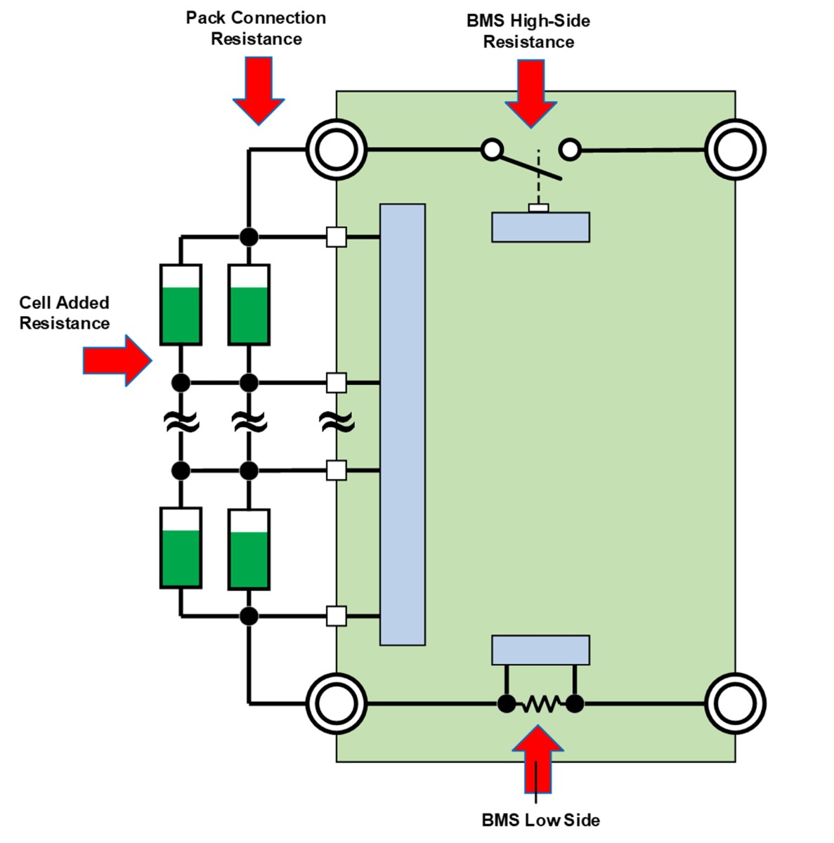
图 10:电池中的电阻
电池组连接电阻(RCXN_PACK 寄存器)是指从电池输出端到 BMS 电路板之间的电阻。该电阻包括正极和负极导线/连接端的电阻。/p>
BMS 高侧电阻(RBMS_HSIDE 寄存器)是由于 PCB 走线和保护 FET 导致的 BMS 高侧总电阻。
BMS 低侧电阻(RBMS_LSIDE 寄存器)是由于采样电阻和 PCB 走线导致的 BMS 低侧总电阻。
电芯附加电阻(RCXN_CELLX 寄存器)是由于电芯之间连接或电芯之间任何母线连接导致的电阻。
电量计 GUI 提供两种方式来设置电芯附加电阻。用户可以将其设置为电池组中所有电芯共用的单一数值,也可以为电池组中的每个电芯分别设置独立数值。如果用户无法测量这些参数,则可以使用默认配置。
电池电压限制
这些设置根据客户应用定义电芯/电池组的最大和最小电压限制。其数值用于空电/满电估算、功率估算以及 SOC 估算。
最大电芯电压(VCELL_MAX 寄存器)是用于 SOC 和满电估算的最大电芯电压。
最小电芯电压(VCELL_MIN 寄存器)是用于 SOC 和空电估算的最小电芯电压。
最大电池组电压(VPACK_MAX 寄存器)是用于 SOC 和满电估算的最大电池组电压。
最小电池组电压(VPACK_MIN 寄存器)是用于 SOC 和空电估算的最小电池组电压。
专家模式
最大电芯电压裕量(VCELL_MAX_MRGN 寄存器)用于覆盖最大电芯电压采样过程中的偏差。
最小电芯电压裕量(VCELL_MIN_MRGN 寄存器)用于覆盖最小电芯电压采样过程中的偏差。
最大电池组电压裕量(VPACK_MAX_MRGN 寄存器)用于覆盖最大电池组电压采样过程中的偏差。
最小电池组电压裕量(VPACK_MIN_MRGN 寄存器)用于覆盖最小电池组电压采样过程中的偏差。
最大/最小电芯和电池组限制仅定义 SOC 为 100% 和 0% 时对应的电压点。电量计将(最大电压 - 裕量)视为可能的满电点,并将(最小电压 + 裕量)视为空电点。这些数值不用于任何保护功能,并且可以与 AFE 中设置的过压(OV)/欠压(UV)阈值不同。
电池电流限制
这些设置根据客户应用定义充电和放电过程中的最大和最小电流限制。所描述的裕量用于覆盖电流采样产生的偏差。
最大放电电流(IDIS_MAX 寄存器)是电池组能够支持的最大放电电流。
最大放电电流(IDIS_MAX 寄存器)是电池组能够支持的最大放电电流。
专家模式
最大放电电流裕量(IDIS_MAX_MRGN 寄存器)用于覆盖电流采样误差。
最大充电电流裕量(ICHG_MAX_MRGN 寄存器)用于覆盖电流采样误差。
负载设置
这些寄存器用于描述负载特性,以提高放电行为预测能力。其参数与用户应用相关,并用于空电预测,以建立电池组 SOC 为 0% 时对应的状态,以及估算剩余空电时间。
标称放电平均电流(IDIS_AVG_SET 寄存器)定义放电期间的平均电流。如果启用了学习功能,该寄存器会自动更新。
标称放电终止电流(IDIS_END_SET 寄存器)定义应用停止放电时对应的电流。如果启用了学习功能,该寄存器会自动更新。
充电器设置
这些寄存器用于描述充电器特性,以提高充电行为预测能力。其参数与客户应用相关,并用于预测电池达到 100% SOC 的时间,这对于满电时间估算非常关键。
标称充电恒流电流(ICHG_CC_SET 寄存器)定义充电过程中的恒流充电电流。如果启用了学习功能,该寄存器会自动更新。
标称充电终止电流(ICHG_END_SET 寄存器)定义充电结束时的电流,即恒压阶段的截止电流。如果启用了学习功能,该寄存器会自动更新。
标称充电恒压电压(VCHG_CV_SET 寄存器)定义恒压(CV)阶段结束时停止充电的电压。如果启用了学习功能,该寄存器会自动更新。
专家模式
充电终止电流裕量(ICHG_END_MRGN 寄存器)定义电流采样的容差裕量,该参数用于满电预测。
为确保准确的满电/空电预测,建议用户使用最精确的充电恒压(CV)和终止电流。这意味着:CV 电压 < 最大电池组电压 <(最大电芯电压 × 电芯数量)。对于完全放电值,建议设置 :(最小电芯电压 × 电芯数量) < 最小电池组电压,以改善限制因素报告。
空电设置/满电设置
在实际应用中,负载电流和充电器电流可能并非恒定。在这些情况下,报告的剩余满电时间/空电时间将持续变化。为了降低瞬态电流对满电/空电估算的影响,电量计包含了一个低通滤波器。
剩余空电时间滤波时间常数(EMTY_RTIME_FILTER 寄存器)用于电流测量的低通滤波器。较高数值表示在剩余空电时间预测过程中会过滤掉更多的电流尖峰。
剩余满电时间滤波时间常数(FULL_RTIME_FILTER 寄存器)用于电流测量的低通滤波器。较高数值表示在剩余满电时间预测过程中会过滤掉更多电流尖峰。
预测空电温度滤波时间常数(EMTY_DTEMP_FILTER 寄存器)用于温度的低通滤波器。较高数值表示突发温度变化对热模型处理过程以及剩余空电时间预测的影响更小。
预测满电温度滤波时间常数(FULL_DTEMP_FILTER 寄存器)用于温度的低通滤波器。较高数值表示突发温度变化对热模型处理过程以及剩余满电时间预测的影响更小。
学习功能
启用学习功能后,电量计可以自动更新某些关键参数。参数更新过程取决于每个学习部分对应的具体规则。
健康状况(SOH)
更新条件如下:
- 状态 == 放电。/li>
- 小温度(SOH_LRN_TMIN)≤ 温度 ≤ 最大温度(SOH_LRN_TMAX)。
- 最小电流(SOH_LRN_IMIN)≤ 电流 ≤ 最大电流(SOH_LRN_IMAX)。
- 最小范围(SOH_LRN_MIN)≤ 新 SOH ≤ 最大范围(SOH_LRN_MAX)。
- 最大增加量(SOH_LRN_DMAX)定义每次更新期间 SOH 最大增加值,而最小增加量(SOH_LRN_DMIN)定义每次更新期间 SOH 最小下降值。
- 增益(SOH_LRN_K)定义 SOH 计算过程中可计入容量变化的增益系数。较小的数值表示 SOH 变化更加平滑。
热传递系数
更新条件如下:
- 状态不等于 REST。
- 平均温度 -(环境温度 + 温度差)≥ 温度变化阈值(HCONV_LRN_DTEMPTH)。更大的数值表示热传递系数变化更加平滑。
- 时间微分值 ≥ 时间变化阈值(HCONV_LRN_DTIMETH)。更大的数值表示热传递系数变化更加平滑。
- 范围(HCONV_LRN_RNG)定义热传递系数的最大变化范围。
- 增益(HCONV_LRN_K)定义热传递系数计算过程中可计入热变化的增益系数。较小的数值表示系数变化更加平滑。
充电恒流(CC)
更新条件如下:
- 电池组 SOC ≤ SOC 阈值(ICHG_CC_LRN_SOCTH)。
- 平均电流变化率 ≤ 电流变化阈值(ICHG_CC_LRN_DITH)。
- 仅当电池组 SOC 小于或等于 ICHG_CC_LRN_SOCTHC,并且在一次电量计迭代期间,电流变化率低于 ICHG_CC_LRN_DITH 的持续时间超过采样计数阈值(ICHG_CC_LRN_CNTRTH)时,学习功能才会启动。
- 更新后的充电恒流(ICHG_CC)值位于标称充电恒流(ICHG_CC_SET)减去充电电流学习范围(ICHG_CC_LRN_RNG),与标称充电恒流(ICHG_CC_SET)加上充电电流学习范围(ICHG_CC_LRN_RNG)之间。
充电终止电流
更新条件如下:
- 电池组 SOC ≥ SOC 阈值(ICHG_END_LRN_SOCTH)。
- 电流 > 电流阈值(ICHG_END_LRN_ITH)。
- 平均电压变化 ≤ 电压变化阈值(ICHG_END_LRN_DVTH)。
- 更新后的充电终止电流(ICHG_END)值位于标称充电终止电流(ICHG_END_SET)减去充电终止电流学习范围(ICHG_END_LRN_RNG),与标称充电终止电流(ICHG_END_SET)加上充电终止电流学习范围(ICHG_END_LRN_RNG)之间。
充电恒压(CV)
更新条件如下:
- 电池组 SOC ≥ SOC 阈值(VCHG_CV_LRN_SOCTH)。
- 电流 > 电流阈值(VCHG_CV_LRN_ITH)。
- 平均电压变化率 ≤ 电压变化阈值(VCHG_CV_LRN_DVTH)。
- 更新后的充电恒压(VCHG_CV)值位于标称充电器恒压(VCHG_CV_SET)减去充电恒压学习范围(VCHG_CV_LRN_RNG),与标称充电器恒压(VCHG_CV_SET)加上充电恒压学习范围(VCHG_CV_LRN_RNG)之间。
放电平均电流
更新条件如下:
- 放电电流 > 电流阈值(IDS_AVG_LRN_ITH)。
- 平均放电电流(IDIS_AVG)学习具有时间常数滤波器(IDIS_AVG_LRN_FILTER)。较大数值表示在学习周期内会对电流尖峰进行更多滤波。
- 更新后的放电平均电流(IDIS_AVG)位于标称放电平均电流(IDIS_AVG_SET)减去平均放电电流学习范围(IDIS_AVG_LRN_RNG),与标称放电平均电流(IDIS_AVG_SET)加上平均放电电流学习范围(IDIS_AVG_LRN_RNG)之间。
放电终止电流
更新条件如下:
- 电池组 SOC ≤ SOC 阈值(IDIS_END_LRN_SOCTH)。
- 放电电流 > 电流阈值(IDIS_END_LRN_ITH)。
- 放电终止电流(IDIS_END)学习具有时间常数滤波器(IDIS_END_LRN_FILTER)。较大数值表示在学习周期内会对电流尖峰进行更多滤波。
- 峰值电流增益(IDIS_END_LRN_KPEAK)定义在计算放电终止电流时,电流峰值对平均放电终止电流的影响程度。如果应用中可能出现较大的电流脉冲,则适当增大该寄存器的值,有助于提高空电点预测的准确性,因为它能够预测空电状态是否会在某次电流脉冲期间发生,而不是在电流接近平均值时才发生。
- 更新后的放电终止电流(IDIS_END)位于标称放电终止电流设置值(IDIS_END_SET)减去放电终止学习范围(IDIS_END_LRN_RNG),与标称放电终止电流设置值(IDIS_END_SET)加上放电终止学习范围(IDIS_END_LRN_RNG)之间。
如果未启用连续学习,电量计会使用上一次循环的数据作为放电终止电流。电量计不会在当前循环完成之前更新该参数。建议启用连续学习功能。
等效串联电阻(ESR)
更新条件如下:
- 电流变化率 ≥ 电流阈值(RESR_LRN_DITH)。
- 标准模式下的最大电阻变化量 < 最大标准模式电阻变化量(RESR_LRN_DRSTD)。
- 扩展模式下的最大电阻变化量 < 最大扩展模式电阻变化量(RESR_LRN_DREXT)。
- 当标准模式最大变化量达到切换至扩展模式所需次数(RESR_LRN_NHIT2EXT)后,电量计会使用更大的限制值。
附加电阻
更新条件如下:
- 电流变化率 ≥ 电流变化阈值(RCXN_CELLS_LRN_DITH)。
- 最小电阻(RCXN_CELLS_LRN_RMIN)≤ 更新后的电芯连接电阻(RCXN_CELLS_LRN_RMAX)。
- RCXN_CELLS_LRN_NAVG 定义 FG 观察电芯连接电阻变化的次数。最终结果将取所有学习发生次数(RCXN_CELLS_LRN_NAVG 次)的平均值。
当启用附加电阻学习时,ESR 学习会自动禁用,直到附加电阻学习完成 RCXN_CELLS_LRN_NAVG 设置的次数;当附加电阻学习完成后,该功能会自动禁用。如果 ESR 初始状态为启用,则会再次启用 ESR。
专家模式
为电量计选择测量数据
MPS 电量计可以配置为无需 AFE 提供特定测量数据即可运行。用户必须启用每次迭代中将提供给电量计的具体测量数据。如果某项读取功能被禁用,则该数值会由电量计内部进行处理,并通过电量计输入寄存器中的对应寄存器输出。
表 1 显示了相关变量。
表 1:FG 读取数据
| 变量 | 相关寄存器 | 备注 |
|---|---|---|
| 电池组电压 | VRDG_PACK_EN | 如果启用,FG 将使用 AFE 的读取值。否则,FG 会对所有电芯电压求和,并增加由已配置电阻引起的压降。 |
| 电池组电流 | IRDG_PACK_EN | 如果禁用,则电池组电流由电芯电流计算得到。 |
| 电芯电流 | IRDG_CELLS_EN | 与电芯电压同步的电流读取值。如果禁用,则该值与电池组电流相同。 |
| 库仑计数 | CCRDG_EN | 如果禁用,则库仑计数根据电池组电流和执行周期计算得到。 |
| 环境温度 | TRDG_AMB_EN | 如果 AFE 具有专用于环境温度的温度读取功能,则可将其作为 FG 输入,以帮助进行热预测。否则,应禁用该读取功能,使 FG 自行估算环境温度。 |
启用电量计学习功能
启用学习功能意味着,当满足学习条件时,电量计会更新配置的参数值(见表 2)。
表 2:FG 功能
| 功能 | 相关寄存器 |
|---|---|
| 健康状况(SOH) | SOH_LRN_EN |
| 等效串联电阻(ESR) | RESR_LRN_EN |
| 电芯连接电阻 | RCXN_CELLS_LRN_EN |
| 充电 CC 电流 | ICHG_CC_LRN_EN |
| 充电终止电流 | ICHG_END_LRN_EN |
| 充电 CV 电压 | VCHG_CV_LRN_EN |
| 放电平均电流 | IDIS_AVG_LRN_EN |
| 放电终止电流 | IDIS_END_LRN_EN |
| 热模型 | THRM_MDL_EN |
| 热传递系数 | HCONV_LRN_EN |
| 最大充电功率 | PCHG_SHW_EN |
| 最大放电功率 | PDIS_SHW_EN |
| 连续放电终止电流 | IDIS_END_LRN_CONT_EN |
| 连续热传递系数 | HCONV_LRN_CONT_EN |
如果启用了连续学习,则电量计会持续将新的学习值更新至寄存器,直到学习过程停止。否则,电量计仅会在学习周期结束时更新该数值。
专家模式
FG 中断选择
MPS 电量计集成了中断功能(IRQ),用于向系统通知多个事件。当一次迭代开始时,IRQ 被置为低电平;如果发生特定事件,则 IRQ 被置为高电平(见表 3)。
表 3:FG 中断
| 中断类型 | 相关寄存器 | 备注 |
|---|---|---|
| 迭代完成 | IT_DONE_INTR_EN | 指示迭代是否已完成。 |
| 状态变化 | STATUS_INTR_EN | 指示电池组状态发生变化(REST、DSG、CHG)。 |
| 空电限制因素 | EMTY_LIM_INTR_EN | 指示空电限制因素发生变化。 |
| 满电限制因素 | FULL_LIM_INTR_EN | 指示满电限制因素发生变化。/span> |
| 电池组 SOC 结果变化 | SOC_PACK_RSLT_INTR_EN | 指示电池组 SOC 发生变化。 |
| 过温警告 | OT_WARN_INTR_EN | 指示是否发生过温情况。 |
| 平均放电电流学习 | IDIS_AVG_INTR_EN | 指示平均放电电流值或学习状态发生变化。 |
| 放电终止电流学习 | IDIS_END_INTR_EN | 指示放电终止电流值或学习状态发生变化。 |
| 充电 CC 电流学习 | ICHG_CC_INTR_EN | 指示恒流充电电流值或学习状态发生变化。 |
| 充电终止电流学习 | ICHG_END_INTR_EN | 指示充电终止电流值或学习状态发生变化。 |
| 充电 CV 电压学习 | VCHG_CV_INTR_EN | 指示充电恒压值或学习状态发生变化。 |
| ESR 学习 | SORESR_CELLS_INTR_EN | 指示 ESR 值或学习状态发生变化。 |
| 电芯连接电阻 | RCXN_CELLS_INTR_EN | 指示电芯连接电阻或学习状态发生变化。 |
| 热传递系数 | HCONV_INTR_EN | 指示热传递系数或学习状态发生变化。 |
| 电芯 SOH 学习 | SOH_CELLS_INTR_EN | 指示 SOH 学习系数或学习状态发生变化。 |
| 放电功率限制因素变化 | PDIS_LIM_INTR_EN | 指示 DSG 功率限制因素发生变化。 |
| 指示 DSG 功率限制因素发生变化。 | PCHG_LIM_INTR_EN | 指示 CHG 功率限制因素发生变化。 |
性能评估
以下示例用于评估电池组 SOC 性能。该过程可在开发过程中使用:在从 0% 到 100% 或从 100% 到 0% 的测试中,绘制理想电池组 SOC 曲线。通过确定曲线的起始点和结束点,可以计算该期间电池增加或减少的容量,从而绘制起点和终点之间的理想曲线。/p>
- 1.测试完成后,从电量计中提取日志数据。读取 CCRDG 寄存器。添加一列(累计容量),将截至当前行之前所有 CCRDG 值累加,以获得截至该行电池增加或减少的容量。
- 2.新增列中的最后一个数值即为本次测试的总容量。
- 3.放电参考 SOC(单位:%)可通过公式(1)计算:
- 4.SOC 误差 =(电池组 SOC - 参考 SOC)。
放电参考 SOC = 100 × (1 - (累计容量[X] / 测试总容量))
充电参考 SOC(单位:%)可通过公式(2)估算:
充电参考 SOC = 100 × (累计容量[X] / 测试总容量)
图 11 显示了 SOC 评估参考。
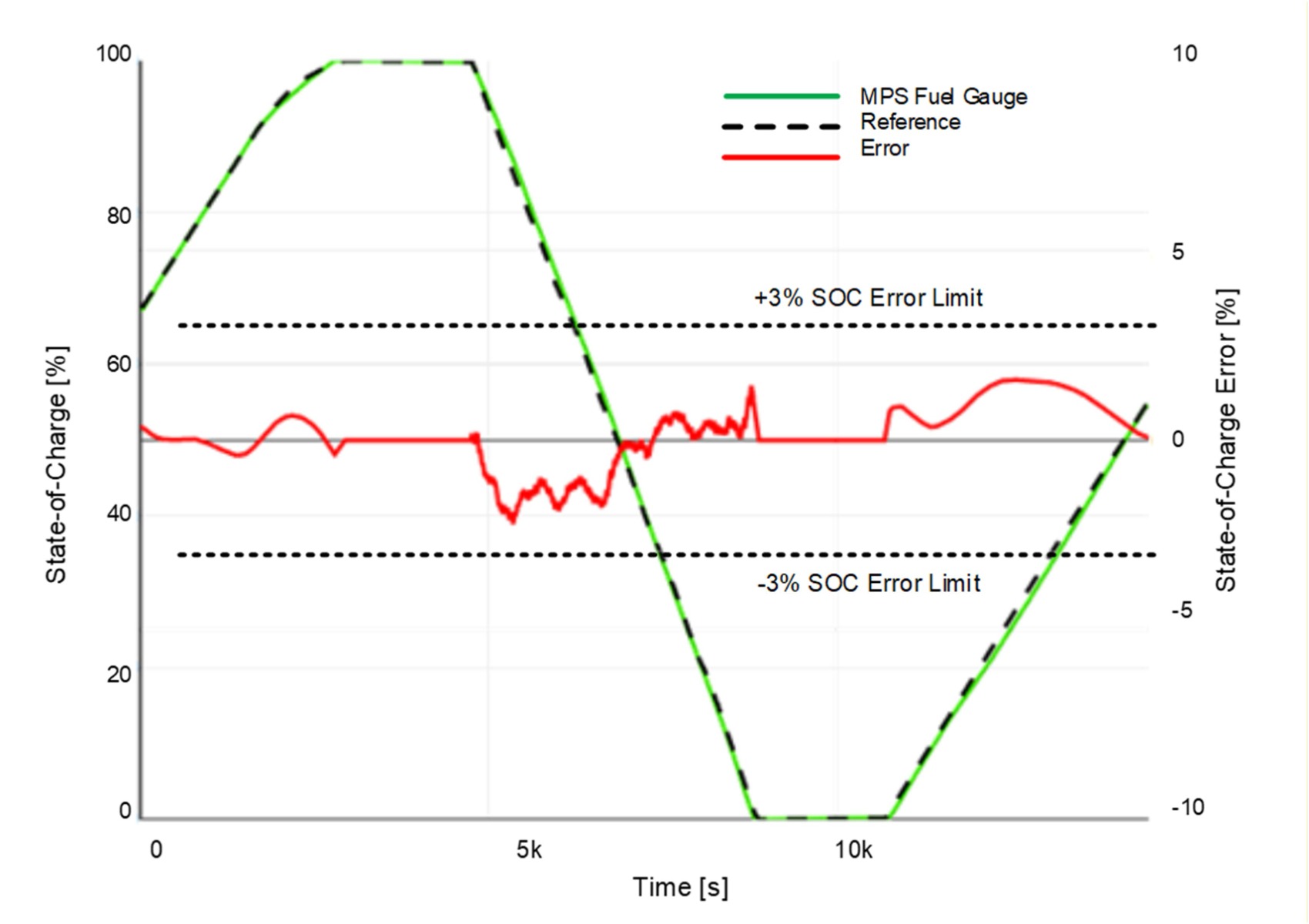
图 11:SOC 评估参考
MPS电量计不仅支持高精度 SOC 计算,还支持电芯老化预测、运行时间估算、可用功率估算以及 ESR 更新。此外,还可用于确定 AFE 中采用哪些适当的电池保护功能,并控制均衡策略。总而言之,MPS FG 可提供一体化解决方案,帮助用户简化开发流程并降低 MCU 资源需求。如需更多信息,请联系 MPS FAE。
技术论坛
 Latest activity a year ago
 5 回复
Latest activity 2 months ago
6 回复
Latest activity 3 years ago
5 回复
5 回复
Latest activity 2 months ago
6 回复
Latest activity 3 years ago
5 回复
直接登录
创建新帐号