AN191 - 如何利用 NTC调节 MPQ7200 的 LED 电流降额

每月为您发送最具参考价值的行业文章
我们会保障您的隐私
摘要
MPQ7200 是一款 42V/1.2A 升降压或 3A 降压同步 LED 驱动器,符合 AEC-Q100 认证,支持汽车前照灯、日间行车灯 (DRL)、转向指示灯和尾灯等应用。汽车前照灯LED通常具有 10W 至 15W 的功率。LED 和 MPQ7200可以共享一个 PCB以提高性价比,但这样设计LED 电源会使 PCB 升温,从而增加MPQ7200 芯片的温度。
本应用说明的目的是提高 MPQ7200 在全光强度下的最高工作温度,并防止因芯片温度过高而导致过温关断。当 MPQ7200 超过一定环境温度(TAMBIENT)时,LED 电流和可见光功率将自动降低。在设计中,MPQ7200 采用外部负温度系数 (NTC) 电阻来测量 PCB 的温度。
本应用说明将讨论,在 TAMBIENT 超过 50°C 时,如何利用汽车前照灯来降低 LED 电流。
简介
MPQ7200 是一款内部集成功率 MOSFET 的高频、恒流、升降压 LED 驱动器。它提供了非常紧凑的解决方案,可实现高达 1.2A 的连续输出电流(IOUT),并在宽输入电源范围内具有出色的负载和线性调整率。MPQ7200 还可以配置为降压模式,以提供高达 3A 的恒定负载电流。
MPQ7200采用恒频迟滞控制以提供超快速瞬态响应,无需环路补偿。在降压模式下,其开关频率(fSW)可设置为高达 2.3MHz的固定频率,以降低电流纹波并改善 EMI。fSW还可以配置为最低 1.15MHz,以在升降压模式下优化效率和散热性能。
MPQ7200具备全面的保护功能,包括过流保护 (OCP)、输出过压保护 (OVP)、输出欠压保护 (UVP)、热降额 (TD) 和过温关断 (TSD)保护。一旦发生故障,故障指示器会输出一个有效逻辑低电平信号。
MPQ7200 只需最少数量的现有标准外部元器件,并采用节省空间的 QFN-19 (3mmx4mm) 封装。
其应用包括汽车前照灯、转向指示灯、雾灯、尾灯、日间行车灯 (DRL)、电池供电手电筒和车灯。
评估板
EVQ7200-L-00A 和 EVQ7200-L-00B 是两款评估板,分别用于展示 MPQ7200 在降压模式和升降压模式下的功能。
本应用笔记将讨论 MPQ7200 的负温度系数 (NTC) 热降额。MPQ7200 以1.15MHz的开关频率在升降压模式下运行。其变体 MPQ7200A具有更低的fSW值(在升降压模式和升压模式下为 410kHz)和不同的 NTC 热降额水平。有关选择 NTC 热降额的更多详细信息,请参阅 MPQ7200 或 MPQ7200A 的数据手册。
图 1 和图 2 分别显示了MPQ7200在降压模式和升降压模式下的布局差异。图 1 为降压模式的 EVQ7200-L-00A 评估板,其无源元件更少。
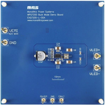
图 1:EVQ7200-L-00A 评估板(降压模式)
| 电路板型号 | MPS IC型号 |
| EVQ7200-L-00A | MPQ7200GLE-AEC1 |
图 2 显示了 升降压模式的EVQ7200-L-00B 评估板。
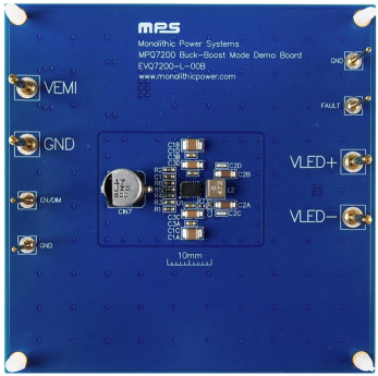
图 2:EVQ7200-L-00B 评估板(升降压模式)
| 电路板型号 | MPS IC型号 |
| EVQ7200-L-00B | MPQ7200GLE-AEC1 |
测量装置
图 3 显示了调节NTC 热调光降额的测量装置。
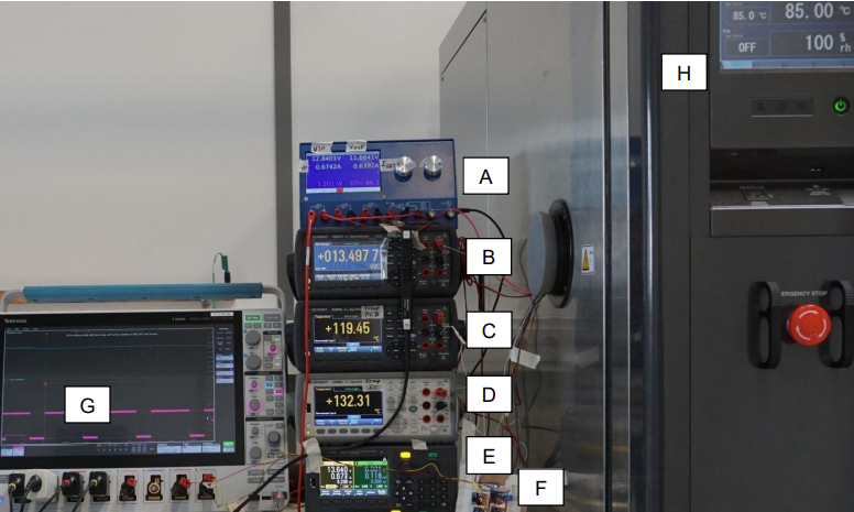
图 3:MPQ7200的NTC 热调光降额测量装置
图3 中的测试设备详细描述如下:
- MPS 效率计(A): MPS 提供的效率计采用四线电压和电流测量 IC 输入电压(VIN_IC)、PCB 输入电流 (IIN)、LED 电压(VLED)和 LED 电流(ILED),为 MPQ7200 提供精确的功耗和效率测量。
- 电压表(B): 电压表测量PCB 输入端子上的输入电压(VIN_PCB)。在本例中,VIN_PCB = 13.5V.
- PCB 热电偶温度计(C): PCB 板载NTC 电阻(RNTC)用于测量PCB 温度,这也是MPQ7200 LED 电流降额的温度信号。粘在 RNTC顶部的外部 NTC 电阻用于测量RNTC的温度。外部NTC 电阻的温度(TNTC)通过万用表读取。
- IC 的热电偶温度计: IC 的热电偶用于测量 MPQ7200 封装顶部的温度(TIC)。使用外部热电偶无法十分精确地测量硅芯片的温度。但使用小型热电偶时,测量误差可以忽略不计。因为封装的顶面是一层塑料薄层,这让硅片和热电偶之间的温差只有几开尔文。
图 4 显示了两种不同的 K 型热电偶。左侧的热电偶是带细线的 Keysight TCK-401301-SE,建议使用导热胶将小型测量目标粘在 PCB 上。右侧的热电偶为采用粗线的通用型,不建议粘在小目标上。
热电偶的线缆由金属制成,用于将热量从测量点传递到气候室的内部和外部环境。这种热传递会导致一定的测量误差,尤其会导致测得的温度低于目标的真实温度。为减少测量误差,建议采用细线热电偶,并在加热室内放置较长的隔热电线。
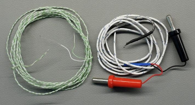
图4: K型热电偶
- 电源(E): 电源用于为 VIN_PCB供电。被测 (DUT) PCB 上有板载 EMC 滤波器,后面跟一个用于反极性保护的肖特基二极管。 VIN_PCB在 EMC 滤波器的输入端测得,VIN_IC在肖特基二极管的输出端测得。
- 外部微调电位器(RPARALLEL) (F): 当放置在气候室外面时,RPARALLEL 可取代 PCB 的表面贴装 (SMT) 电阻,将 NTC 热调光的降额起点设置为所需的环境温度(TAMBIENT,约为50° C).
图 5 显示了 RPARALLEL 的实验装置。通过该实验,可以找到恰当的 RPARALLEL 电阻,与 RNTC并联放置。
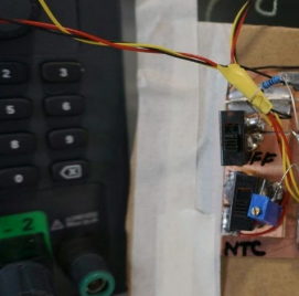
图 5:RPARALLEL 将NTC 热降额起始值调节为 TAMBIENT = 50°C
- 示波器(G)(ILED 和引脚 19 的 VNTC (VNTC2)): G 用于精确测量 VNTC2的最高方波幅度。最高幅度为模拟 NTC 热降额提供温度相关信息。该示波器采用电流探头测量 ILED 并显示计算出的 RMS 值。ILED 的波形特征可通过示波器进行监控。需注意的是,效率计能够以更高精度测量RMS值。
- DUT气候室(H): 气候室用于控制 TAMBIENT,还能利用安装在纸箱上方几厘米处的传感器来控制气流温度。
图 6 显示了封住被测 PCB 的纸箱,纸箱可隔绝气候室中的气流。整个 PCB 在没有空气流通的情况下被测试,其他产品也是如此。
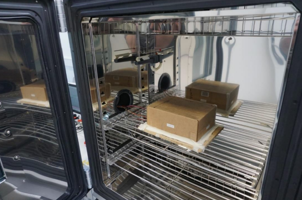
图 6:气候室中位于封闭纸箱下的被测 PCB
如何调节热降额
将被测设备置于所需的 TAMBIENT (50°C)下并调节RPARALLEL,直到最大 ILED (ILED_MAX)开始从其典型值的 100% 下降到一个较低的值。NTC 调光降额可以表示为比率(DIMRATIO) 或百分比。其原理图和组件的详细信息,请参见图 7 、图 8 及图 9。
DIMRATIO 百分比可以用公式 (1) 来计算:
$$DIM_{RATIO} [\%] = 100 \times \frac {I_{LED MAX}}{I_{LED}}$$根据 ILED_MAX,最大 RMS ILED在 50°C TAMBIENT下低于降额起始点,且LED 在 TAMBIENT下测得。
热电偶和电阻
本节内容将介绍PCB 上的电阻 RNTC、RPARALLEL,以及热电偶。本应用说明采用了 47kΩ的 RNTC (at TNTC= 25°C)和负温度系数来检测 PCB 上的TNTC。将 RNTC放置在距离 MPQ7200 几厘米的位置,通过RNTC 设置 DIMRATIO。这样得到的是模拟 ILED 电流降额,而不是脉宽调制 (PWM)降额。
将一个K 型热电偶粘在 RNTC顶部,并通过数字万用表的温度刻度读取热电偶信号。另一个 K 型热电偶则测量 MPQ7200 的顶部封装温度。图 7 显示了两个放置在 IC 封装和RNTC上的K 型热电偶。
放置在 IC 封装和RNTC上的热电偶。
其中RP定义为 TNTC = 25°C时,RPARALLEL (20.89kΩ) 和 RNTC (47kΩ)的并联电阻。这些测量的目的是找到实验 RPARALLEL。在测量中,RPARALLEL由外部微调器设置。对于之后的系列PCB,RPARALLEL充当SMT电阻。
图 8 显示了电阻和 TNTC之间的关系。
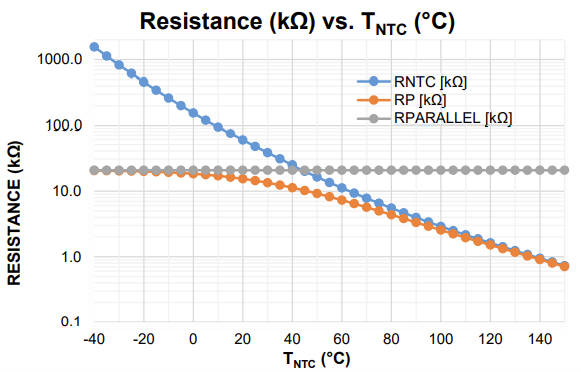
图 8:曲线特性(RNTC、RNTC||20.89kΩ 和 RPARALLEL vs. TNTC)
RNTC 覆盖了宽非线性电阻范围。RPARALLEL 在 TA ≥ 50°C 时改善了线性化,并在 TAMBIENT = 50°C时设置所需的调光降额起点。注意,TNTC 大于 TA,因为 PCB 被 11W 的 LED 电功率加热。
热降额原理
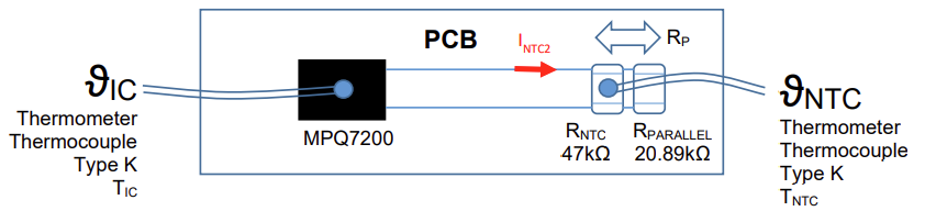
图 9 显示了调节 MPQ7200 的模拟 NTC ILED降额所需的电阻。
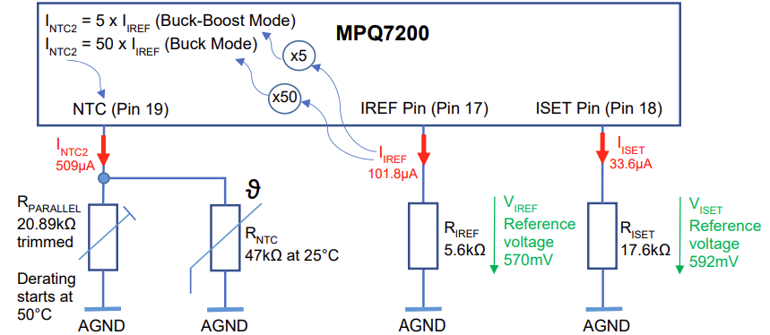
图9: NTC热降额调节
请下载完整 PDF以了解 NTC 热降额调节所需的关键组件。
结语
MPQ7200 是一款灵活的 ILED 驱动器,专为外部元件数量少且 BOM 成本低的应用而设计。该器件具有丰富的内置功能,为控制 ILED提供了充分的灵活性。
在本应用笔记中,NTC ILED 降额扩展了可用的 TA 范围,即使在最坏情况下也是如此,即LED 电源对 PCB 进行加热时(PCB 上有4个 LED 和 MPQ7200 )。4个 LED 的功耗可通过公式 (7) 来计算:
$$Four-LED Power Loss = 12.15V \times 0.909A = 11W$$可以得出,IC 和电感的功耗为 1.8W。
NTC 热调光降额提供了一种经济高效的解决方案,其中两个热源还可以共享一个 PCB。
_______________________
您感兴趣吗?点击订阅,我们将每月为您发送最具价值的资讯!
技术论坛
 Latest activity 2 years ago
 10 回复
Latest activity 2 years ago
4 回复
Latest activity a year ago
10 回复
10 回复
Latest activity 2 years ago
4 回复
Latest activity a year ago
10 回复
直接登录
创建新帐号