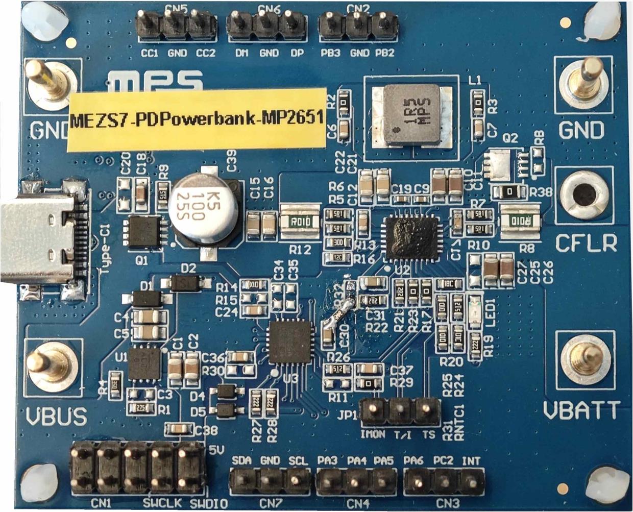
MEZS7-PDPowerbank-MP2651 参考设计

概述
MEZS7-PDPowerBank-MP2651 是一款适用于双角色端口(DRP)应用的完整电源解决方案模块,它集成了两款MPS器件:MP2651 和 MPF52002。
MP2651 是一款升降压充电器 IC,适用于 1 节至 4 节串联电池组,支持 4V 至 22V的宽输入电压(VIN)范围。在源模式下,IN 引脚可支持5V 至 21V 的宽输入电压范围,满足 USB 供电(PD)规范,同时支持高分辨率输出电流限制。
MPF52002 则是一款高度集成的 USB PD 控制器。它集成了 32 位 ARM Cortex-M0 微控制器(MCU),适用于 DRP 或受电(sink)端口。该控制器支持 DRP 应用的自动 DRP 切换功能,且符合 PD3.1 规范。在源模式下,该器件支持 PD3.1、BC1.2、Apple 分压器模式、华为FCP/SCP 以及 QC2.0/3.0 协议。
该板集成了一个 DRP USB Type-C 端口,并支持 PD3.1 和 BC1.2 协议。当接入适配器时,该端口作为受电端口工作,可提供最高 6A 的充电电流为电池充电。当连接负载时,该端口作为源端口工作,由电池为 USB VBUS 供电。
性能概述 (1)
除非另有说明,以下规格参数均基于 TA = 25°C 条件。
| 参数 | 条件 | 默认值 |
| 受电(Sink)模式 | ||
| 输入电压 (VIN) 范围 | 4V 至 22V | |
| 输入电流(IIN) 限制 | 最高可达 5A | |
| 电池充电调节电压 (VBATT_REG) (2) | 8.4V | |
| 快充电流 (2) | VIN = 9V 至 20V | 3A |
| 典型充电效率 | VIN = 20V, VBATT = 8V, ICC = 3A |
92.2% |
| 源(Source)模式 | ||
| 电池电压范围 (VBATT) | 最高可达 18.68V | |
| 源模式输出电压 (VIN_SRC) (3) | 5V 至 21V | |
| 默认 PDO 输出 (2) | 5V/3A, 9V/3A, 15V/1.8A, 20V/1.35A, 5V至5.9V/3A, 5V至11V/3A, 5V 至16V/1.8A | |
| 源模式典型效率 | VBATT = 8V, VIN_SRC = 9V, IIN_SRC = 2.6A | 93.6% |
1) 欲了解更多详情,请参阅 MP2651 数据手册;
2) 这些参数可通过 I2C 接口在 MPF52002 上进行配置;
3) 这些参数由 MPF52002 根据协议自动配置。
评估板
长x宽x高 (6cmx5cmx2.1cm)
| 评估板型号 | MPS IC 型号 |
| MEZS7-PDPowerBank-MP2651 | MPF52002GRE-0001 |
| MP2651GVT-000A |
表 1:电池电芯数量设置(4)
| 电芯数量 | PB2 | PB3 |
| 2芯(默认) | 1:浮空或高电平 | 1:浮空或高电平 |
| 3芯 | 0:短接至 GND | 1:浮空或高电平 |
| 4芯 | 1:浮空或高电平 | 0:短接至 GND |
4) 设置 PB2 和 PB3 ,在为实际电池充电前配置好电芯数量。
快速入门指南
MEZS7-PDPowerBank-MP2651 解决方案模块专为 USB PD 应用而设计,它配备一个 DRP USB Type-C 端口。充电电流预设为 3A,满电电压预设为 8.4V(适用于 2 节串联锂离子电池)。在反向源模式下,输出预设为 5V/3A 或 27W PD。
系统启动之后,用户可通过 I2C 接口将自定义的充电参数设置下载至 MPF52002 的易失性存储器中;但器件断电时,易失性存储器中的数据将会被清除(复位)。这些参数也可下载至 MPF52002 的非易失性存储器(NVM)中;NVM 中的数据即使在器件断电后也不会丢失。
按照下列步骤连接电池以进行测试:
- 连接串联电池组的端子:
- 正极 (+): VBATT
- 负极 (-): GND
- 若使用电池模拟器:
- 预设电池电压,然后关闭模拟器;
- 连接电池模拟器输出端子:
- 正极 (+): VBATT
- 负极 (-): GND
- 开启电池模拟器。
- PD3.1 V1.8
- 对于非 PD 适配器,总线电压(VBUS)为 5V。默认输入电流(IIN)限制为 900mA。若电源端 CC 端子上连接有 RP 电阻,则根据 RP 电阻的阻值,IIN 限制可提高至 1.5A 或 3A。
- PD3.1 V1.8
- DCP
- Apple 模式
- 将 CN3 接口上的 INT 引脚(PB1)短接至 GND
- 将 USB Type-C 设备或电源适配器连接至 USB Type-C 端口
- 主机SCL时钟频率为400kHz(快速模式),符合100kHz至400kHz的时钟规范
- 每条指令仅支持读取或写入1个字节。MPF52002不支持多字节的读/写操作
- 建议在两条 I2C 指令之间设置10ms或更长的延时。
在插入电源适配器之前,请务必确认 PB2 和 PB3 的设置正确(见图 1)。否则,系统负载和电池可能会因此受损。
受电(Sink)模式
MPF52002 会根据适配器所支持的协议,自动请求最大输入功率 (PIN)。使用 USB Type-C 转 USB Type-C 线缆,或 USB Type-A 转 USB Type-C 线缆,将 USB Type-C 端口连接至电源适配器。MP2651 的输入电流(IIN)限制以及适配器的输出电压(VOUT)将根据协议自动进行设置。随后,器件将启动充电操作。对于双节电池应用,默认电池满电调节电压为 8.4V,充电电流限制设定为 3A。
该评估板上 MPF52002 的默认固件在受电模式下支持以下协议:
充电电流可能会受输入功率(PIN)的限制。如果适配器的最大输出功率低于 MEZS7-PDPowerbank-MP2651 的输出功率(POUT),IIN 限制环路将自动调节充电电流,避免电源适配器过载。
图 1 展示了受电模式下的设置。
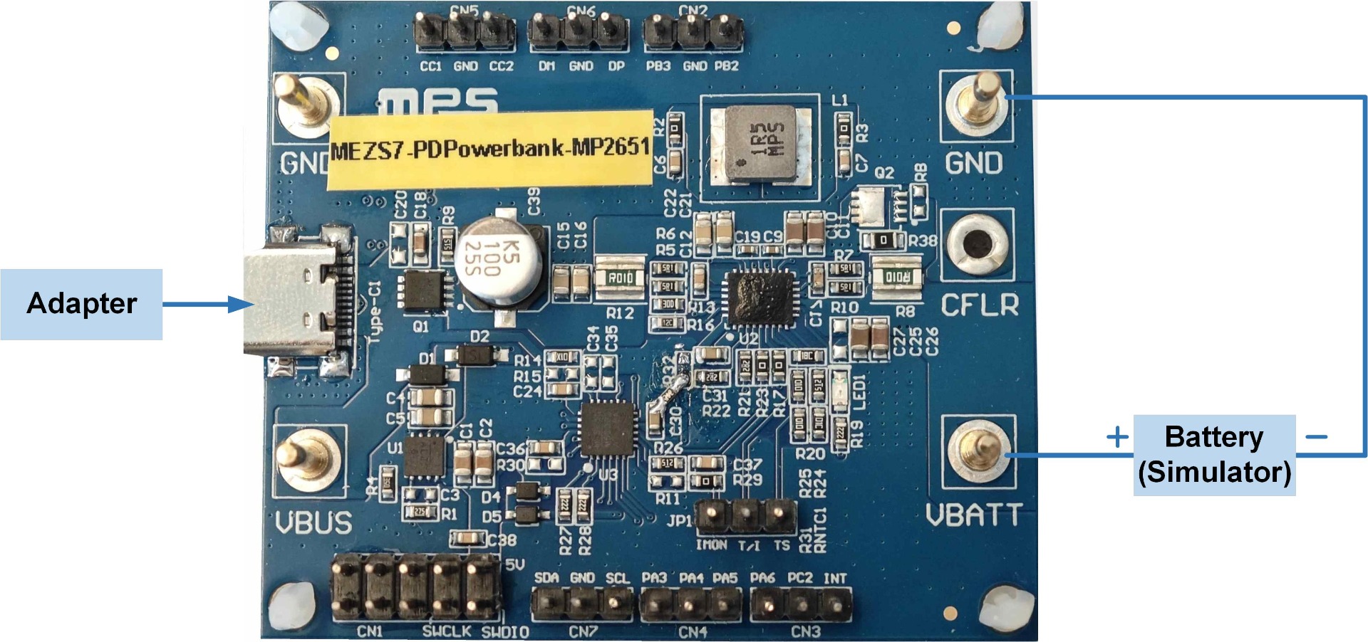
图 1:受电模式设置
源模式
使用 USB Type-C 转 Type-C、USB Type-C 转 Micro-B 或 USB Type-C 转 Lightning 连接线,将设备连接至 USB Type-C 端口。源模式可自动启动,并根据设备需求提供相应的电压。
本评估板上 MPF52002 的默认固件在源模式下支持以下协议:
VBUS会自动启动,其电压值由 PD 协议分析仪或移动设备设定。PD 协议分析仪可选择不同的 PDO 输出。默认 PD 输出功率 (POUT) 为 27W。电池放电电流限制为 6.4A。
图 2 展示了源模式的设置。
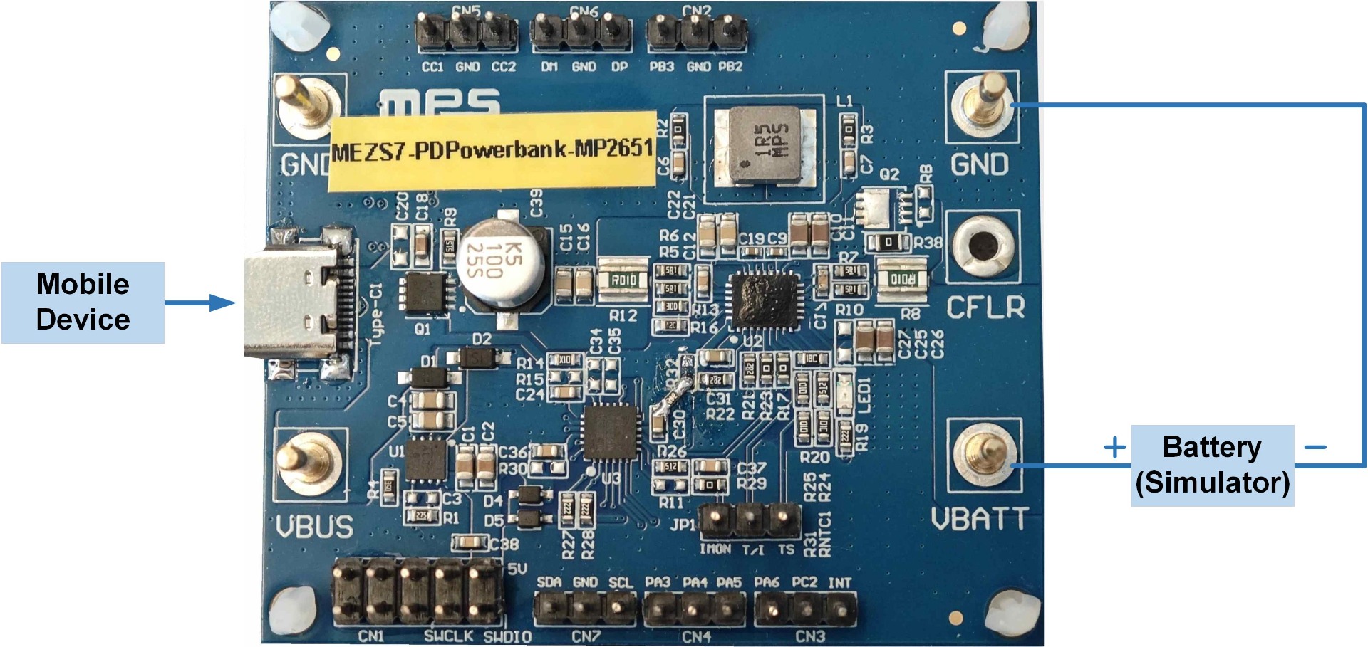
图 2:源模式设置
I2C 从机功能说明
MP2651 和 MPF52002 可通过 MPF52002 与 I2C 主机之间的 I2C 接口进行控制或监测。主机应通过 PB6 和 PB7 连接至 MPF52002,而非直接连接至 MP2651(见图 3)。MPF52002 会周期性地读取充电参数,通报 MP2651 的状态,并将相关信息更新至 I2C 从机寄存器中。此外,主机也可通过 MPF52002 向 MP2651 发送特定的 I2C 指令。

图 3:MPF52002 I2C 从机功能框图
I2C 连接硬件设置
在仅电池供电模式下,MPF52002 可进入深度睡眠模式以节省电能,此时其 I2C 从机寄存器处于禁用状态。若需重新启用 I2C 从机功能,可采用以下两种方法:
接下来,使用 EVKT-USBI2C-02 通信接口板 (5) 将 PC 与 MEZS7-PDPowerbank-MP2651 相连接(见图 4)。其中,I2C SCL 信号线应连接至 PB6 引脚(该引脚丝印标记为 SWDIO),I2C SDA 信号线则应连接至 PB7 引脚(该引脚丝印标记为 SWCLK)。
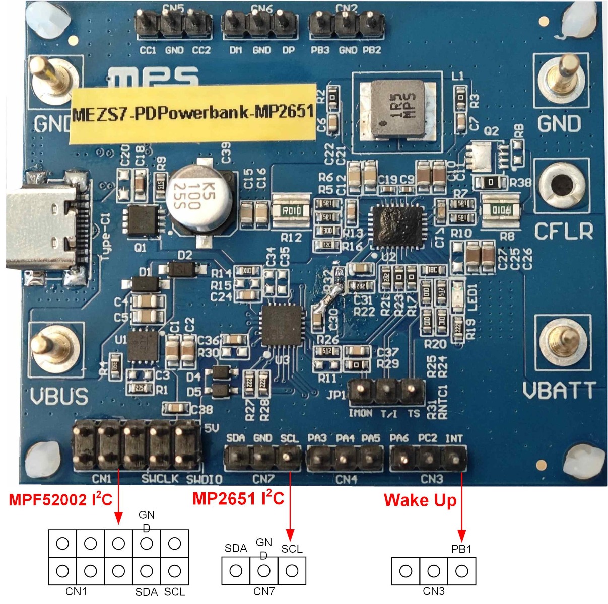
图4:I2C 通信硬件连接示意图
5) 请联系MPS现场应用工程师(FAE),或通过MPS网站提交申请,以获取EVKT-USBI2C-02通信接口板。
I2C 主机时间要求
评估板原理图 (6) (7)
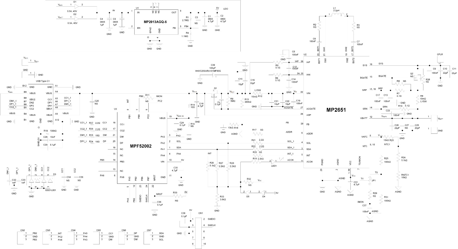
图5:评估板原理图
6) 可以在R9上并联一个0.1μF的电容(Cx),以避免ACGATE导通MOSFET Q1时产生浪涌电流。
7) PB6/7可用作SWD接口。在使用SWD接口下载新固件之前,请将PA3(boot 0)拉低以重启MPF52002。固件更新完成后,断开PB6/7与SWD接口的连接并释放PA3,随后开启设备以加载新固件。
MEZS7-PDPowerbank-MP2651 物料清单
| 数量 | 参考编号 | 数值 | 描述 | 封装 | 制造商 | 制造商型号 |
| 2 | C1, C2 | 4.7μF | 陶瓷电容, 16V, X7R | 0805 | Murata | GCM21BR71C475KA73L |
| 5 | C3, C20, C27, C34, C35 | NS | ||||
| 2 | C4, C5 | 1μF | 陶瓷电容, 25V, X7R | 0603 | Wurth | 885012207078 |
| 13 | C6, C7, C8, C12, C13, C14, C17, C23, C24, C29, C36, C37, C38 | 100nF | 陶瓷电容, 25V, X7R | 0603 | Wurth | 885012206071 |
| 2 | C9, C19 | 100nF | 陶瓷电容, 25V, X7R | 0402 | Murata | GRM155R71E104KE14D |
| 4 | C10, C11, C25, C26 | 22μF | 陶瓷电容, 25V, X5R | 0805 | Murata | GRM21BR61E226ME44L |
| 4 | C15, C16, C21, C22 | 10μF | 陶瓷电容, 25V, X7S | 0805 | Murata | GRM21BC7E106KE11L |
| 1 | C18 | 4.7μF | 陶瓷电容, 25V, X5R | 0603 | Murata | GRM188R61E475KE11D |
| 1 | C28 | 10nF | 陶瓷电容, 25V, X7R | 0603 | TDK | C1608X7R1E103K |
| 2 | C30, C31 | 4.7μF | 陶瓷电容, 16V, X5R | 0603 | Murata | GRM188R61C475KE11D |
| 2 | C32, C33 | 1nF | 陶瓷电容, 25V, C0G | 0603 | Murata | GRM1885C1E102JA01D |
| 1 | C39 | 100μF | 混合型, 25V, 20mΩ | SMD | Nippon Chemi-Con | HHXC250ARA101MF80G |
| 1 | R1 | 2.7MΩ | 薄膜电阻, 1% | 0603 | Yageo | RC0603FR-132M7L |
| 5 | R2, R3, R17, R23, R29 | 0Ω | 薄膜电阻, 5% | 0603 | Yageo | RC0603JR-070RL |
| 1 | R4 | 1.1MΩ | 薄膜电阻, 1% | 0603 | Yageo | RC0603FR-071M1L |
| 4 | R5, R6, R7, R10 | 5.1Ω | 薄膜电阻, 1% | 0603 | Yageo | RC0603FR-075R1L |
| 2 | R8, R12 | 10mΩ | 电流采样电阻,1%,长边,1W | L1508 | Film Tech | RL3720WT-R010-F |
| 1 | R9 | 5.1MΩ | 薄膜电阻, 5% | 0603 | Yageo | RC0603FR-075M1L |
| 5 | R11, R15, R30, R32, RB | NS | ||||
| 1 | R13 | 200kΩ | 薄膜电阻, 1% | 0603 | Yageo | RC0603FR-07200KL |
| 3 | R14, R34, R35 | 10Ω | 薄膜电阻, 1% | 0603 | Yageo | RC0603FR-0710RL |
| 1 | R16 | 13kΩ | 薄膜电阻, 1% | 0603 | Yageo | RC0603FR-0713KL |
| 3 | R18, R25, R31 | 100kΩ | 薄膜电阻, 1% | 0603 | Yageo | RC0603FR-07100KL |
| 3 | R19, R27, R28 | 2.2kΩ | 薄膜电阻, 5% | 0603 | Liz | CR0603JA0222G |
| 1 | R20 | 15kΩ | 薄膜电阻, 1% | 0603 | Yageo | RC0603FR-0715KL |
| 4 | R21, R22, R36, R37 | 2.2Ω | 薄膜电阻, 1% | 0603 | Yageo | RC0603FR-072R2L |
| 2 | R24, R26 | 5.1kΩ | 薄膜电阻, 1% | 0603 | Yageo | RC0603FR-075K1L |
| 1 | R33 | 3.6kΩ | 薄膜电阻, 5% | 0603 | Liz | CR0603JA0362G |
| 1 | R38 | 0Ω | 薄膜电阻, 5% | 0805 | Yageo | RC0805FR-070RL |
| 1 | RNTC1 | 10kΩ | 薄膜电阻, 1% | 0603 | Yageo | RC0603FR-0710KL |
| 7 | JP1, CN2, CN3, CN4, CN5, CN6, CN7 | 2.54mm | 3引脚,单排 | DIP | Wurth | 61300311121 |
| 1 | CN1 | 2.54mm | 5引脚,双排 | DIP | Wurth | 61301021121 |
| 1 | TYPE_C1 | USB | USB Type-C 插座,16引脚 | SMD | Yuehu Electronics | PC-071603863-R |
| 4 | VBUS, GND, VBAT | Φ2.0 | 铜引脚 | DIP | ||
| 1 | CFLR | NS | ||||
| 1 | LED1 | Red | LED | 0805 | Wurth | 150080RS75000 |
| 2 | D1, D2 | IR = 20µA | 肖特基二极管,0.5A | SOD123 | AUK | SDB0540 |
| 1 | D3 | 5V | ESD二极管 | SOT-363 | onsemi | ESD1L001 |
| 2 | D4, D5 | VF = 0.4V when IF = 1mA | 60V, 15mA | SOD-323 | Diodes, Inc. | SD101AWS |
| 1 | Q1 | 8.5mΩ | MOSFET | PowerPAK1212-8 (3.3mmx3.3mm) | Vishay | SISA14DN-T1-GE3 |
| 1 | Q2 | NS | MOSFET | |||
| 1 | L1 | 1.5μH | 电感,9.7mΩ,9A | SMD | MPS | MPL-AL5030-1R5 |
| 1 | U1 | MP2013A | 低功耗线性稳压器 | QFN-8 (3mmx3mm) | MPS | MP2013AGQ-5 |
| 1 | U2 | MP2651 | 适用于1至4节串联电池组的升降压充电器IC | TQFN-30 (4mmx5mm) | MPS | MP2651GVT-000A |
| 1 | U3 | MPF52002 | 高度集成的USB PD控制器(内置32位ARM Cortex-M0微控制器) | QFN-24 (4mmx4mm) | MPS | MPF52002-0001 |
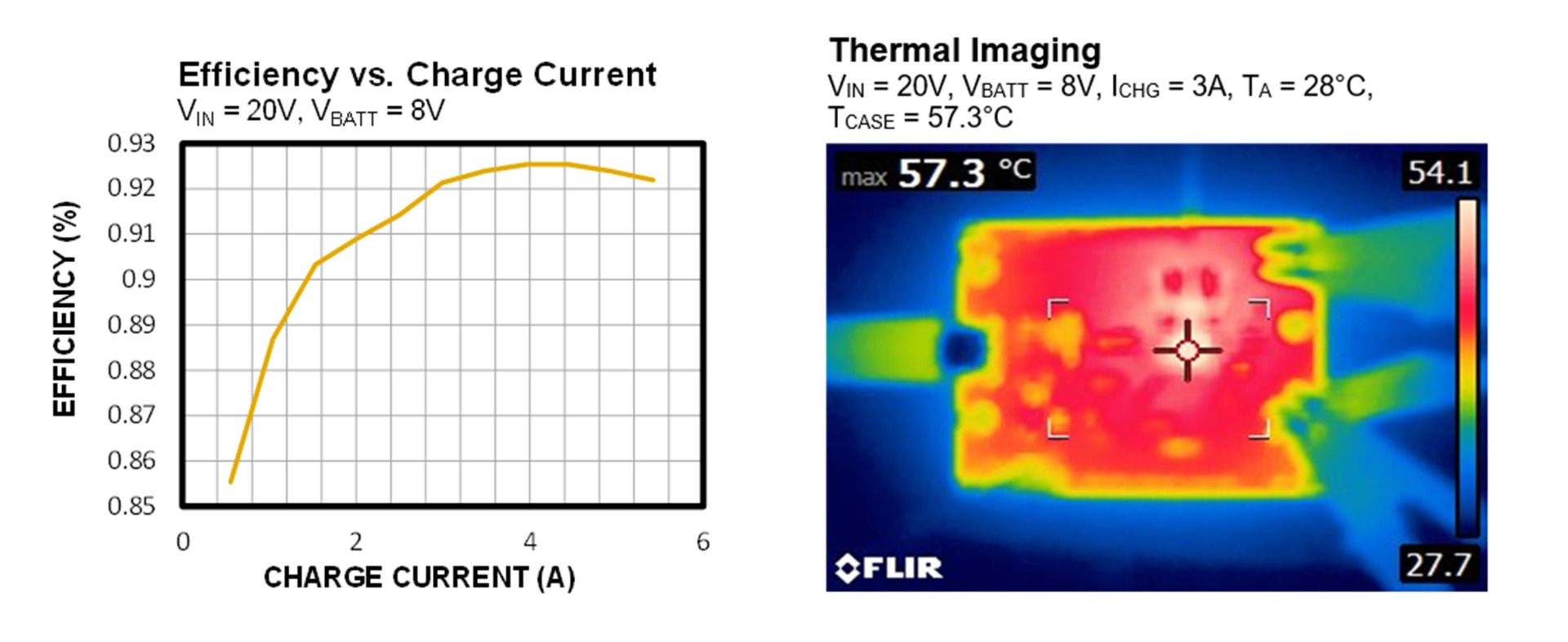
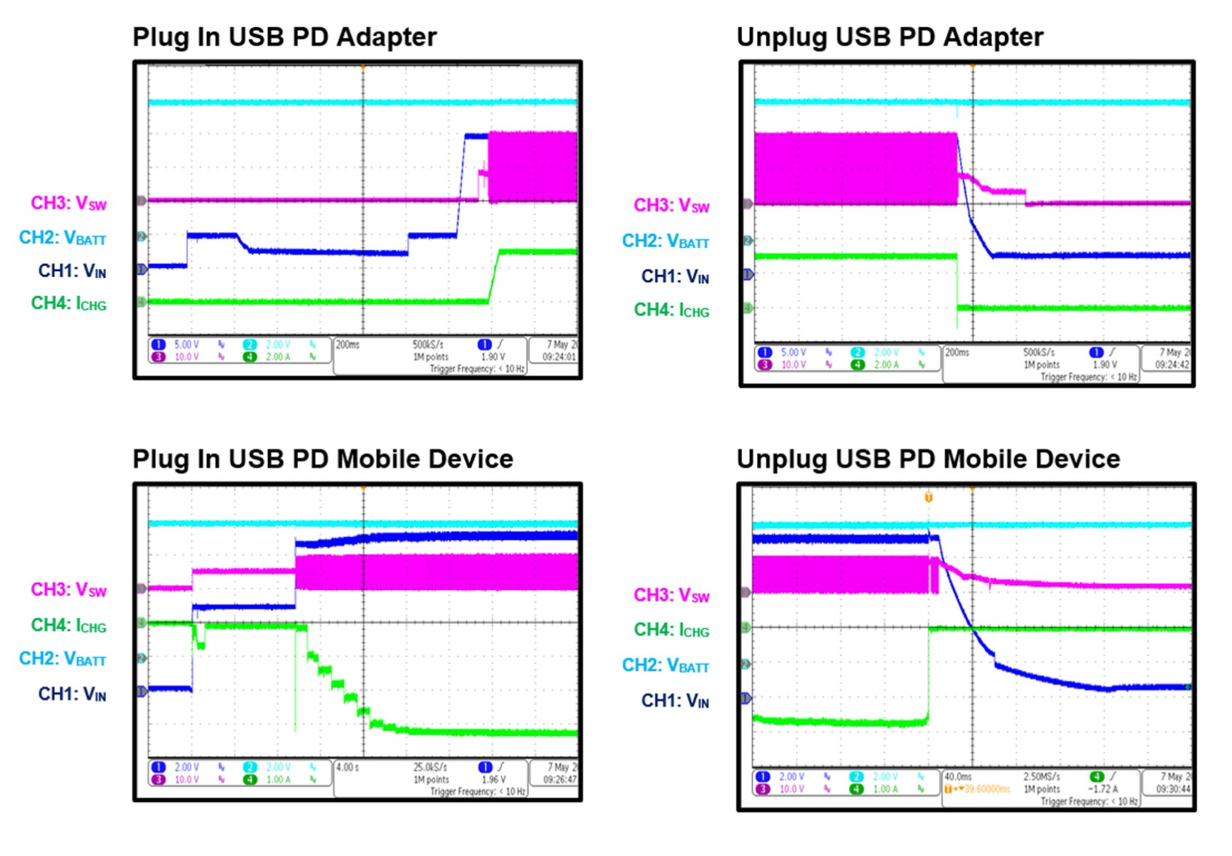
EVB 测试结果
性能曲线及波形均在评估板上测得。输入电源为 USB PD 适配器,测试条件:VIN = 20V, VBATT = 8V, TA = 25°C,寄存器数据均采用默认设置(除非另有说明)。
PCB布局
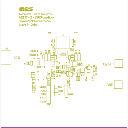
图6:顶层
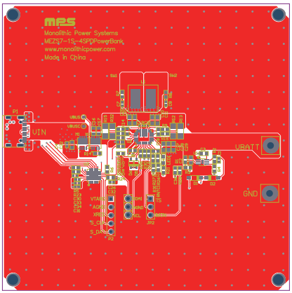
图 7:中间层 1
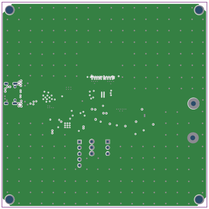
图8:中间层2
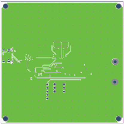
图9:底层
直接登录
创建新帐号