MP2659 参考设计:12V 铅酸电池充电解决方案

1 概述
1.1 简介
铅酸电池凭借其电压稳定、价格低廉、维护简单、可靠性高等优点被广泛应用于电池供电设备中。 然而,市场上却鲜有专为铅酸电池充电应用设计的芯片。
本参考设计展示了一种铅酸电池充电解决方案。该解决方案采用了MPS高度集成的开关充电器IC,MP2659。该器件专为配备 3 节至 6 节串联锂离子或锂聚合物电池组的便携式设备而设计。
1.2 功能特性
- 高达 36V 的工作输入电压
- 不开关时最大耐受电压可达 45V
- 高达 3A 充电电流
- 支持1节12V 铅酸电池
- 0.5% 的参考电压精度
- 输入电流限制调节
- 最小输入电压调节
- 充电操作指示
- 电量耗尽的电池组恢复
- 电池过压保护(OVP)
- 可调安全定时器
- 电池 NTC 温度监控器
1.3 应用
- 工业医疗设备
- 电动工具
- 机器人和便携式吸尘器
- 无线扬声器
2 参考设计
2.1 功能框图
图 1显示了用于铅酸电池的高度集成开关充电器IC功能框图。该应用具有 40W 的输出能力和高达 36V 的输入电压;同时支持调整分压器电阻以调整铅酸电池的调节电压。
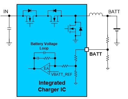
图 1:功能框图
2.2 相关解决方案
本参考设计基于以下 MPS 解决方案:
| MPS IC | 描述 |
| MP2659 | 集成 MOSFET的36V独立开关充电IC,适用于3节至 6节串联电池组应用 |
表1: 系统规格
2.3 系统规格
| 参数 | 规格 |
| 输入电压范围 | 4.5V 至 36V |
| 输出电压 | 高达 14.4V |
| 最大输出电流 | 3A |
| 开关频率 | 680kHz 或 350kHz(标称条件下) |
| 效率 | >92% |
表2: 系统规格
3 设计
3.1 设计方法
图 2 显示了一个具有“或”选择电源路径管理功能的铅酸电池充电应用电路。该电路的功率级包含一个电感(L1)和三个电容 (CIN、 CPMID和CBATT)。通过添加适当的外部元件,可以实现带电源路径管理的完整充电功能。

图2: 应用电路
“或“选择电源路径管理可以通过两个 P 沟道 MOSFET 和其他组件(例如 ZD1、ZD2、D1 和电阻)来实现。没有输入源时,QBATT导通并将能量从电池传输到系统;有输入源时,QBATT关断,系统电源由来自 QIN的输入源提供。
MP2659 专为 3 节至 6 节串联锂离子和锂聚合物电池而设计。每节电池都具有稳定的电池电压,如3.6V、4.15V、4.2V 或 4.35V。要实现铅酸电池的充电,可以使用电阻分压器(R1 和 R2)来设置特定的稳定电池电压。R1 和 R2 可通过公式(1)来计算:
$$\frac {R_{2}} {R_{1} + R_{2}} = \frac {V_{BATT\_REG}} {V_{BATT\_TERM}}$$其中 VBATT_REG = 电池数量 x VBATT_CELL(VBATT_CELL由 CELL 和 VB 引脚设置);VBATT_TERM是铅酸电池的充电截止电压;R1的范围应介于 2kΩ 和 5kΩ 之间。
3.2 原理图

图 3:MP2659 解决方案原理图
图 3 显示了 MP2659 解决方案原理图。具体实现过程中,请遵循以下指南:
- 1. 该电路可在 VIN < 20V 的应用中安全工作。
- 2. 对于 VIN 超过 20V 的应用,需在 VIN 和 GND 之间添加一个 ≥47µF 的电解电容,并在VIN和 PMID之间添加一个具有较大电流容量的肖特基二极管(例如 B240A)。 如果电压尖峰达到 45V,则采用 TVS 二极管以钳位 VIN 电压。
- 3. 电池插入期间 PMID 上的电压尖峰也要纳入考量。如果该电压尖峰达到 45V,则添加一个额外的 TVS 二极管以钳制 PMID 电压。
- 4. 该评估板上的电感只适用于 fSW = 680kHz 或 ICC < 2.2A 的应用;对于 fSW = 350kHz 和 ICC > 2.2A的应用,应选择具有更高电感或更高饱和电流的电感。
- 5. 有关组件选择的更多信息,请参阅 MP2659 数据手册。
针对 VIN超过 20V 的应用,推荐组件如下表所列。
| 引脚 | 条件 | 建议 |
| IN | ≤20V 输入 | 在IN 引脚上添加一个 1µF/50V 陶瓷电容用于适配器应用;添加一个 ≥47µF 的电容用于太阳能应用。 |
| >20V 输入 | 在 IN 引脚上添加一个 47µF/50V 电解电容。如果在 VIN 热插入测试期间 IN 电压超过引脚的最大额定电压,则需要添加一个 TVS 二极管。 | |
| BATT | 3节或4节 | 在 BATT 引脚上添加一个 10µF/50V 陶瓷电容。 |
| 5节或6节 | 在 BATT 引脚上添加一个 TVS 二极管或 ≥47µF 的电解电容。 | |
| PMID | - | 在 PMID 引脚上添加一个 2.2µF/50V 陶瓷电容(首选 1206)。 在 IN 和 PMID 之间添加一个 2A/40V 肖特基二极管。 如果 VBATT 热插入测试期间 PMID 电压超过引脚的最大额定电压,则需要添加一个 TVS 二极管。 |
表4: 组件选择
下载 PDF
直接登录
创建新帐号