MP3385B - 4-String, 80V Output WLED Controller with I2C Interface
Summary
The MP3385B is a high-performance step-up controller designed by Monolithic Power Systems, Inc. (MPS) for driving WLED arrays in mid-sized and large-sized LCD panel backlighting applications. This controller provides electrical engineers with an efficient, reliable, and flexible solution for designing advanced LED backlight systems.
Key Features:
- Wide Input Voltage Range (4.5V to 33V): The MP3385B supports a wide input voltage range, enabling it to be compatible with a variety of power sources used in different applications.
- 80V Absolute Maximum Rating for Each String: With an 80V maximum rating for each LED string, the MP3385B can drive high-power LED arrays for bright and uniform backlighting.
- 1.8% Current Matching Accuracy between Each String: This feature ensures uniform brightness across all LED strings, resulting in high-quality backlighting performance.
- Unused Channel Auto-Detection during Start-Up: The MP3385B can automatically detect and disable unused LED strings during start-up, preventing unnecessary power consumption and potential damage to the LEDs.
- Configurable Switching Frequency (100kHz to 900kHz): This feature allows engineers to optimize the performance of the LED driver based on their specific application requirements.
- Multiple Dimming Modes: The MP3385B supports various dimming modes selectable via the I2C interface, providing flexibility in meeting different application requirements for brightness control.
- Full-Scale Current and LED Dimming Range Configurability: Engineers can configure the full-scale current with 8-bit resolution and the LED dimming range with 10-bit resolution for internal dimming mode, enabling precise control of LED brightness.
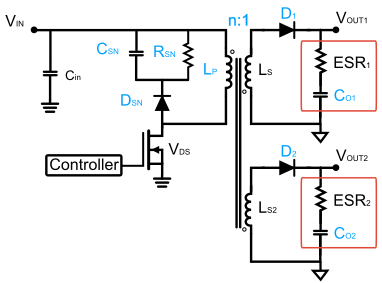
- Cascading Capability with a Single Power Source: This feature allows multiple MP3385B controllers to be connected and powered from a single power source, simplifying the design of larger backlighting systems.
- Comprehensive Protection Features: The MP3385B includes numerous protection features, such as over-current protection (OCP), over-voltage protection (OVP), under-voltage protection (UVP), thermal shutdown, LED short and open protection, and inductor and diode short protection, ensuring safe and reliable operation.
Value Proposition:
The MP3385B offers a compelling value proposition for professional electrical engineers designing LED backlight systems for LCD panels. Its wide input voltage range, high output voltage rating, and current matching accuracy enable efficient and uniform LED backlighting performance. The multiple dimming modes, configurable switching frequency, and cascading capability provide flexibility in addressing various application requirements.
The comprehensive protection features integrated into the MP3385B ensure the safe and reliable operation of the LED driver, which is crucial in maintaining the longevity and performance of the LED backlighting system. In summary, the MP3385B provides a high-performance, versatile, and reliable solution for driving WLED arrays in mid-sized and large-sized LCD panel backlighting applications.

System
Transformer
Output Capacitor
RCD Snubber
Control
System Specification
Input
Output
System
Operation
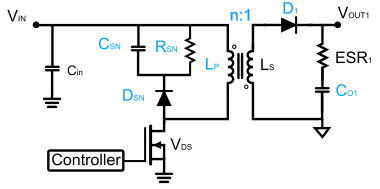
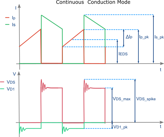
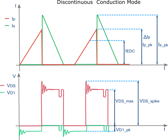
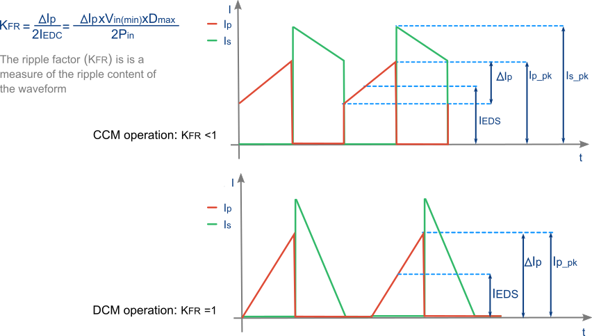
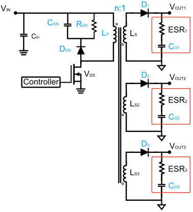
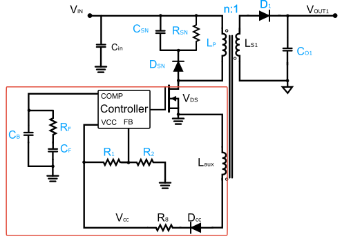
The flyback converter uses a coupled inductor with a gapped core and its inductor design depends on the inductor current operation mode, see waveforms above.
Continuous Conduction Mode (CCM) advantages
- - Lower peak primary and rectifier currents
- - Lower input and output capacitance
- - Improved EMC properties
- - Lower transformer core losses
Discontinuous Conduction Mode (DCM) advantages
- - Lower primary inductance
- - Smaller transformer possible
- - Easier to compensate (no RHPZ)
- - Fastest transient response
- - No rectifier reverse-recovery losses
- - Lower FET turn-on losses
Transformer
Transformer Primary Inductance
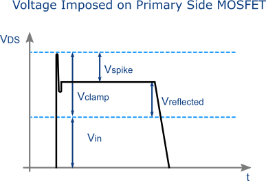
Leakage inductance is caused by the magnetic flux from one winding in a transformer that does not couple perfectly to other windings. It depends largely on the physical winding geometry. The leakage inductance in a Flyback transformer negatively affects the power conversion efficiency.
This leakage energy may result in a high voltage spike on the drain of the main switch, which should be restricted to protect the MOSFET and is primarily dissipated either in in a turn-off snubber like a RCD clamp network as heat.
The ripple factor is closely related with the transformer size and the RMS MOSFET current. The conduction loss in the MOSFET can be reduced reducing the ripple factor, but too small a ripple factor means an increase in transformer size.
Output Capacitor
Output Capacitance
Equivalent Series Resistor
Output capacitors are highly stressed in flyback converters so the main factors to take into account when specifying the output capacitors are: capacitance value, ripple current, low ESR , temperature, voltage rating and lifetime. If lower output ripple is required, a larger output capacitor must be used with lower ESR.
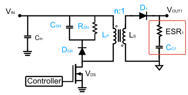
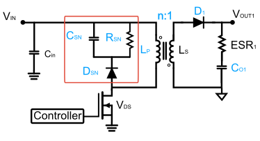
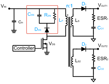
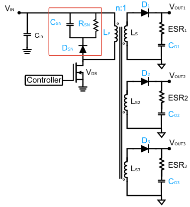
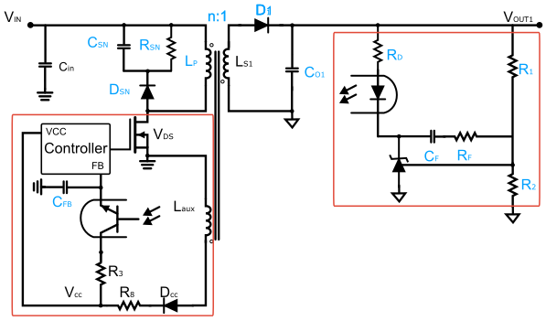
RCD Snubber
Snubber Capacitor
The snubber helps to mitigate the voltage spikes that occur due in ringing between transformer 's leakage inductor and stray capacitances in the circuit at the switching node. Without the snubber, the voltage spikes add noise and can even cause MOSFET breakdown.
If spikes occur, tune the value of the snubber resistor value until optimal performance is found. The resistor of the RCD clamp always dissipates power, even when there is no power in the main converter.
The use of a relatively large capacitor keeps the voltage constant over a switching cycle and even with very little load on the converter, the capacitor will always be charged up to the voltage reflected from the secondary of the converter.
Control
System
Voltage Divider
Primary Side Regulation (PSR) is easier to implement and requires fewer components, whereas Secondary Side Regulation (SSR) allows for more advanced regulation techniques such as weighted regulation.
Regarding transient response speed, SSR is faster than PSR because the output voltage in PSR is only sampled when the switch Q1 is off.
Regarding reliability, isolation in PSR is solely dependant on the transformer's isolation, whereas SSR isolation also depends on the optocoupler. Therefore, PSR eliminates the risk of malfunction due to failures in the optocoupler.
Power
Input Capacitor
Power Switches
Transformer Primary Inductance
Output Capacitor
RCD Snubber
Control
直接登录
创建新帐号