DOWNLOAD PDF VERSION
Application Note
Using MagAlpha™ Devices to Sense BLDC Rotor Position
Introduction
Brushless DC (BLDC) or electronically commutated (EC) motors require feedback to the controlling electronics to indicate the position or angle of the rotor. Traditionally, this has been done using three hall sensors to sense the field of the magnets mounted on the rotor. This type of feedback provides enough information to commutate the motor, but it gives only 60° resolution. This is inadequate to measure the rotational position or to measure motor speed accurately, especially at low speeds. To over come these shortcomings, often an optical rotary encoder is employed in addition to hall sensors. This provides good speed and position accuracy, but it requires an extra electromechanical part that is quite expensive and somewhat unreliable. A better solution is to sense the rotor position directly, using a Sensima MagAlpha™ magnetic angle sensor mounted in proximity to the rotor magnets.
The MagAlpha™ Device
The Sensima MagAlpha™ device is an IC that can sense directly the angle of an external magnetic field. These devices use proprietary techniques to measure the angle of the file with up to 11 bits of accuracy at very high speed. The angle information can be presented in a number of ways, including being read directly through a serial (SPI) port. Also, the devices provide outputs that emulate the quadrature outputs of an optical encoder, as well as the “UVW” signals usually generated by the three hall sensors used in a BLDC motor. Commonly, magnetic angle sensors are used with a 2-pole magnet oriented above the surface of the IC (shown on the left in the image below). In addition, the MagAlpha™ devices include side-shaft compensation, which allows them to measure accurately the angle of a magnet placed to the side of the device (shown on the right in the image below).
Sensing the Rotor Magnets
If a MagAlpha™ device is mounted near the side of the rotor, the angle of the rotor’s magnetic field – and therefore the rotor‘s mechanical angle – can be measured. The drawing below shows the magnetic field around a 4-pole rotor, with a MagAlpha™ device mounted in close proximity. You can see that as the rotor turns, the angle of the magnetic field cutting through the MagAlpha™ device rotates.
As is the case when employing three hall sensors, the sensor measures one full rotation for each pair of poles. In other words, each mechanical revolution of the shaft causes one electrical revolution per pole pair to be reported by the device; this is exactly what is needed for commutation. Unlike many competitive devices, the MagAlpha™ sensor is extremely fast – the position is calculated every 2 µS, with a latency of 3 µS. This allows accurate commutation at very high rotor speeds – a 3 µS latency results in a ~1% commutation error at a 3kHz electrical frequency (or about 100,000 RPM for a 4-pole motor). This is actually faster than many simple hall sensors!
The “zero” angle position of the MagAlpha™ device is programmable. During manufacturing, a simple step in calibration puts the rotor in a known position and sets the zero position of the device. This is stored in nonvolatile memory inside the device, replacing the labor-intensive manual positioning needed with optical encoders. Also, it allows an electrical adjustment of commutation advance.
Mounting
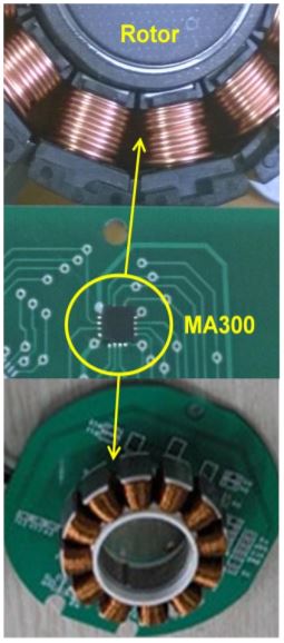
Often, BLDC motors include a PCB mounted inside the motor to support the hall sensors (and often the motor controller/driver as well). If the rotor magnet structure is sufficiently close to the PCB, a MagAlpha™ device can be mounted directly on that PCB, in a position similar to one that would be used for three discrete hall sensors. Since the MagAlpha™ devices are very small (3mm x 3mm x 0.9mm), often they can be placed in between pole pieces. Examples of mounting on a PCB for both inner-rotor and outer-rotor motors are shown below.
Note that even if it is physically impossible to mount a MagAlpha™ device inside the motor, all the advantages of the device are gained by mounting a separate disc or ring magnet on the motor shaft, as shown below.
When using three hall sensors for commutation, the sensors need to be mounted accurately or mis-commutation can occur, resulting in torque ripple and inefficient operation. When using the MagAlpha™ device, the magnetic field angle is sensed in one location only. Commutation signals (always exactly 120° apart) are generated from that angle, so sensor mounting accuracy is not as critical as it is with three separate hall sensors. This improves production yield loss and rework due to mis-positioned hall sensors.
MagAlpha™ Interfacing
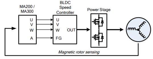
MagAlpha™ devices output signals directly that emulate the UVW hall signals, as well as outputs that emulate the quadrature signals of an optical encoder. These signals can be used to replace the hall sensors and optical encoder directly for position controlled applications or an “FG” or tachometer signal for speed controlled applications. In fact, the MagAlpha™ device can replace directly the hall sensors and speed/position encoder and still utilize the existing motor controller and driver circuitry, as shown below.
Using MagAlpha to Improve Performance of Existing Controller/Driver
For even higher performance, a microcontroller can be employed to read directly the rotor electrical angle (with up to 11 bits of resolution) via the SPI interface of the MagAlpha™ device. Since the rotor position is known with great accuracy in real time, a simple lookup-table based algorithm can be used to generate the PWM signals for each phase. This simplifies the implementation of sinusoidal commutation.
Performance and Cost Advantages
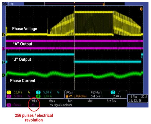
In position-controlled applications, the MagAlpha™ sensor provides equal or better resolution to an optical encoder, at much lower cost. Also, it is insensitive to dirt and dust that commonly plague optical encoders in industrial applications, causing position detection errors and eventually system failures. In speed-controlled applications, the accurate angle measurement can be used to generate a high-pulse-count tachometer signal (up to 256 pulses per electrical revolution), as shown below. This is ~10-20x of what can be obtained using electromagnetic tachometers (“FG”) commonly used in highvolume BLDC motors.
Conclusion
Sensima MagAlpha™ devices can be used to replace hall sensors and optical encoders in BLDC motors, providing cost and performance benefits. Often, the device can be mounted directly inside the motor and sense the rotor position, without the need of additional magnets.
直接登录
创建新帐号