AN192 - 零延迟脉宽调制控制(ZDPTM)

每月为您发送最具参考价值的行业文章
我们会保障您的隐私
摘要
本文将为大家介绍MPS独特的固定频率电源控制方法——零延迟脉宽调制 (PWM) 控制 (ZDPTM)。相比常见的固定频率控制方法,如电压模式控制或峰值电流模式控制,ZDPTM可明显改善瞬态响应。
简介
对电源设计而言,MPS 的零延迟 PWM(ZDPTM)控制具备很多优势,包括快速瞬态响应和稳定的开关频率(fSW)。我们先来简单回顾一下常见的控制拓扑,如电压模式控制、电流模式控制和恒定导通时间(COT)控制。然后再详细介绍零延迟 PWM(ZDPTM)控制,并用实例来展示 ZDPTM 相比于传统控制方法的具体优势。
传统控制方法
电压模式控制
电压模式控制是最简单的控制方法之一,如图 1所示。
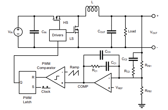
图1: 电压模式控制
这种控制方法首先将反馈电压与参考电压之间的差异(VREF - VFB)放大来生成误差信号(通常为补偿电压);然后将该误差信号与电压斜坡进行比较,以生成功率级的占空比。电压模式控制需要高 ESR 电容或Type III补偿网络来稳定系统。其控制增益也与输入电压(VIN)成正比,这会导致交叉频率随VIN的变化而变化。为了避免这种情况,斜坡电压需要与VIN成正比。
峰值电流模式控制
峰值电流模式控制是汽车电源最常用的控制方法之一,如图 2所示。
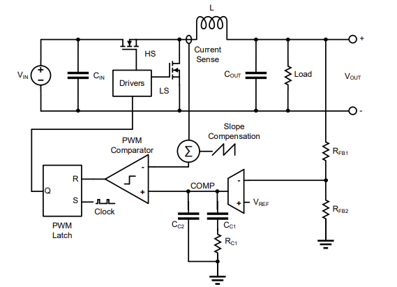
图2: 峰值电流模式控制
与电压模式控制类似,VREF - VFB差值被放大以产生误差信号。但峰值电流模式控制将该误差信号与电感电流(IL)进行比较,后者通常通过镜像 MOSFET、采样电阻或无损电流采样电路进行采样。通常,峰值电流模式拓扑还包含一个斜率补偿信号,以消除Buck 电路占空比超过50%时产生的次谐波震荡。将测得的 IL 合并到环路中可以降低补偿的复杂性,并且仅需要Type II补偿。这同时消除了控制增益对 VIN 的影响;也就是说,交叉频率在整个 VIN 范围内能够保持相对恒定。
但在峰值电流模式拓扑中,电流信号在开关转换期间并不稳定。一旦上管 MOSFET (HS-FET) 导通,PWM 比较器需要短时间的消隐。相比电压模式控制、传统 COT 或 ZDPTM,这会导致更长的最小导通时间(tON_MIN)。
采用峰值电流模式控制的MPS 器件包括 MPQ2167、MPQ4436、MPQ4323 和 MPQ4430。
传统恒定导通时间(COT)控制
高性能应用常采用传统COT 控制来改善瞬态性能,如图 3 所示。
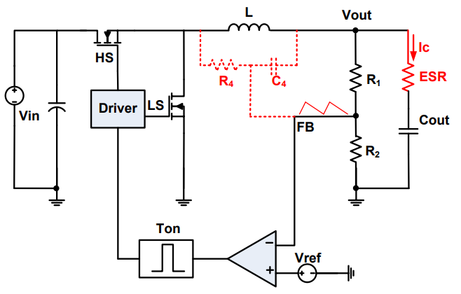
图3: 传统COT控制
传统 COT 控制会直接比较 VFB 与 VREF 以触发导通脉冲,但它要求反馈信号纹波与 IL同相。实现二者同相的方法包括输出电容 ESR、跨电感放置的斜坡注入电路或内部生成的合成斜坡。当 VFB 降至低于 VREF 或误差信号时,将生成导通时间脉冲,并馈入栅极驱动器。在大瞬变期间生成的连续导通时间脉冲具备内部最小关断时间,可快速恢复输出电压 (VOUT)。因此,相比电压模式控制和电流模式控制,COT控制改善了负载瞬态响应。
为了优化比较器造成的输出电压的偏移,可以增加误差放大器去提高输出电压精度。
负载瞬态响应期间可能会出现连续的导通时间脉冲,这将导致 fSW 在操作期间暂时升高。对比较关注 EMI 性能的应用而言(例如严格要求 EMI 性能以降低系统串扰的工业或汽车电子产品),这会带来问题。
采用COT 控制的MPS 器件包括 MPQ2179、MPQ2172 和 MPQ3431A。
零延迟PWM 控制 (ZDPTM)
架构
零延迟 PWM (ZDPTM) 控制可实现媲美传统 COT 控制的负载瞬态性能,而且采用固定频率方案,如图 4所示。
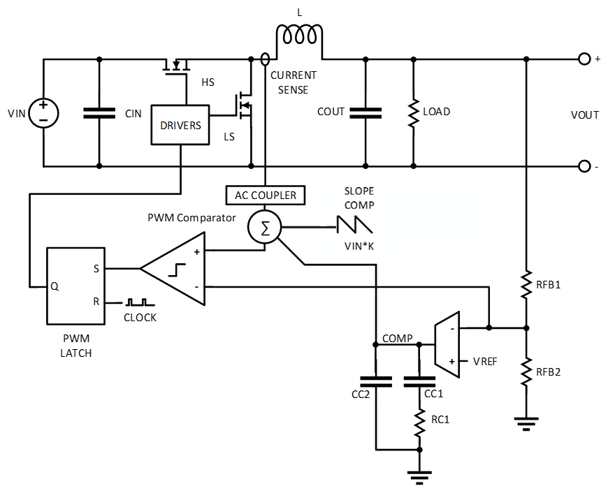
图4: 零延迟 PWM (ZDPTM) 控制
与传统COT相比,ZDPTM 通过EA得到稳定的输出电压,同时又将FB信号引入到环路控制里,提高了负载变化的响应速度。这条路径可快速改变驱动 HS-FET 和下管 MOSFET (LS-FET) 的占空比,无需另外调节斜坡大小,即可补偿 VOUT 的波动。例如,当 VOUT 因大负载瞬变而降低时,占空比会在下一个导通周期内增加,以便为输出电容供电,从而恢复 VOUT 。在这个过程中,ZDPTM无需调节fSW(见图 5)。
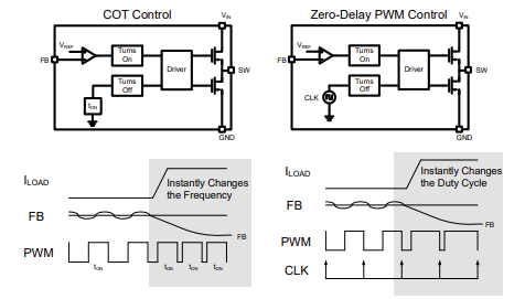
图 5:传统 COT 控制与 ZDPTM 的比较
ZDPTM 控制通过误差放大器(VREF - VFB)产生误差信号。该信号与AC耦合电流信号和斜率补偿斜坡相加。然后将求和信号与 VFB进行比较,并馈入使用固定频率时钟作为复位信号的 PWM 锁存块。ZDPTM 环路稳定性可通过Type II 补偿实现;与Type III补偿相比,ZDPTM节省了设计周期时间。
ZDPTM 还实现了谷值电流检测。与峰值电流模式控制不同,使用 ZDPTM 检测谷值电流不需要对上管采样增加消隐时间,它可以在 LS-FET 导通时对电流进行采样,所以ZDPTM可以实现更小的 tON_MIN。因为 VIN:VOUT比率更大、fSW更高,器件能够以更低的占空比运行。
采用ZDPTM控制的MPS 器件包括 MPQ4340、MPQ4371 和 MPQ2286。
仿真结果(1)
图 6 显示了 MPQ4340 的负载瞬态仿真结果。
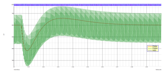
图6: MPQ4340负载瞬态响应
其中PWM-为反馈信号; PWM+ 是补偿信号、AC耦合电流采样和斜率补偿的总和;HSG为高端栅极启动信号。
可以看到,在经历输出负载从 0A 变为 4A 引起的下冲和轻微低频过冲之后,VOUT迅速恢复。VOUT恢复过程始终与 PWM- 成正比。
一旦 PWM+ 超过 PWM-,HSG 就会导通(见图 7)。
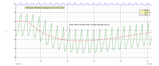
图7: HSG 在 MPQ4340 负载瞬态响应期间的导通
一旦 VOUT下降,HSG 脉冲宽度就会增加,以向输出提供更多能量,并在负载阶跃后校正 VOUT。
图 8 显示了负载增加后占空比的变化;与此同时,fSW仍保持恒定。
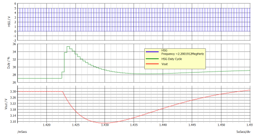
图 8:MPQ4340 负载瞬态响应期间的占空比变化
图 8 中的绿色迹线表示HSG(如图 6 、图 7 所示)的占空比(以 % 为单位)。占空比在几个开关周期内从 27% 增加到 35%,以减少由负载增加引起的 VOUT压降,从而使 VOUT 快速恢复。图 8 中的蓝色迹线表示,在整个负载瞬态变化期间,恒定 fSW(2.2MHz)下的HSG。
通过生成模拟波特图,我们可以观察该控制方法的稳定性(见图 9)。
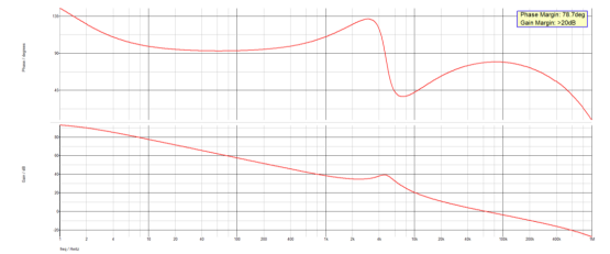
图9: MPQ4340波特图
其相位裕度和增益裕度优于大多数的设计目标。交叉频率约为 63kHz。由于采用了快速路径,大信号瞬态响应优于 63kHz 交叉频率的预期响应。但如我们在传统 COT 控制中常见的一样,与传统峰值电流模式控制器件的波特图比较并不能精确地反映负载瞬态响应的改善。
测试条件:
1) VIN = 12V,VOUT = 3.3V,50A/µs 时 0A 至 4A 负载阶跃,fSW = 2.2MHz,L = 1µH,COUT = 2 x 22µF,模拟电容电压降额,在 MPQ4340 上进行测试。
零延迟 PWM(ZDPTM)控制的优势
与其他固定频率控制方法(例如电压模式控制和峰值电流模式控制)相比,零延迟 PWM (ZDPTM)控制快速路径可以显著改善瞬态响应。图 10 显示了 ZDPTM控制(MPQ4340)和峰值电流模式控制(MPQ4430)之间的 0A 至 3.5A 负载瞬态响应比较。MPQ4340 和 MPQ4430 具有相同的电感、电容和 fSW。
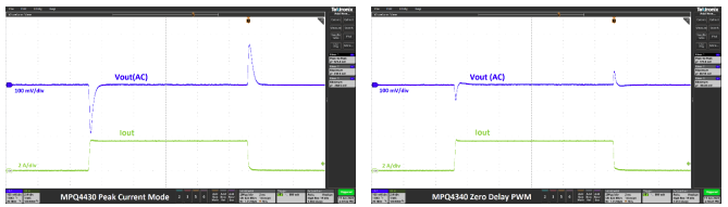
图10: ZDPTM 与峰值电流模式控制的负载瞬变比较
上图的波形显示了MPQ4430的523mVPK-PK负载瞬态和MPQ4340的170mVPK-PK负载瞬态。可以看出,MPQ4340 的瞬态响应明显优于 MPQ4430,这让用户可以在使用更少输出电容的同时改善瞬态性能。
谷值电流可以实现非常短的 tON_MIN。尽管采用峰值电流模式控制的器件 tON_MIN已经可以很低(介于 60ns 和 100ns 之间),但 MPQ4340 的最长tON_MIN也仅为 35ns。因此,MPQ4340 可以将扩展汽车电池电压(高达 18V)直接转换为 1.8V,同时可在高于 AM 的频段上切换,并提供频谱扩展 (FSS)调制。
固定频率则使 ZDPTM 具备出色的频率稳定性。采用 ZDPTM 控制的器件(例如 MPQ4340)还能与外部时钟同步或提供频谱扩展(FSS)调制。ZDPTM 非常适合汽车等EMC 要求苛刻的应用。
结语
与传统的峰值电流模式控制相比,零延迟 PWM (ZDPTM) 控制提高了负载瞬态性能,同时还能在负载瞬变期间保持固定频率。固定频率是 ZDPTM 与传统COT 控制的主要区别,后者具有波动的 fSW。ZDPTM 还具有更短的 tON_MIN,这让器件可用于需要高 fSW 和低占空比的应用。通过对采用 ZDPTM控制 的MPS 产品进行仿真和硬件测试,以上优势均已得到验证。
_______________________
您感兴趣吗?点击订阅,我们将每月为您发送最具价值的资讯!
技术论坛
 Latest activity 2 years ago
 10 回复
Latest activity 2 years ago
4 回复
Latest activity a year ago
10 回复
10 回复
Latest activity 2 years ago
4 回复
Latest activity a year ago
10 回复
直接登录
创建新帐号