Synchronous Motors
Synchronous motors are a type of alternating current (AC) motor in which the rotation of the shaft is synchronized with the frequency of the supply current when the motor is in a steady state. The period of rotation precisely matches the period of the AC waveform. This particular property sets these other types of motors apart from induction motors, which often exhibit some slip between the rotor speed and the electrical current frequency.
Detailed Design and Operational Characteristics
Both a rotor and a stator are components that make up synchronous motors. The stator, similar to the stator of an induction motor, produces a revolving magnetic field in the air gap. Unlike the rotor of an induction motor, the synchronous motor's rotor either energizes with direct current (DC) or incorporates permanent magnets, creating a fixed magnetic field.
Rotor Types: There are a few different types of rotors that can be used in synchronous motors. One of these is the salient pole type, in which the rotor poles are composed of steel laminations and are attached to the rotor hub. This specific rotor design physically separates the rotor poles from each other. Each pole also carries a concentrated excitation winding. Alternators that have four poles or more often make use of the salient pole rotor. Alternators can also be of the non-salient (cylindrical) kind, in which the rotor is a smooth cylinder made of solid forged steel and has a number of slots on its outer periphery. The rotor positions its winding in these slots. Because there are no poles projected on the surface of the cylindrical rotor, it does not have any scratches. This ensures that there is a consistent air gap between the stator and the rotor in the alternator unit.
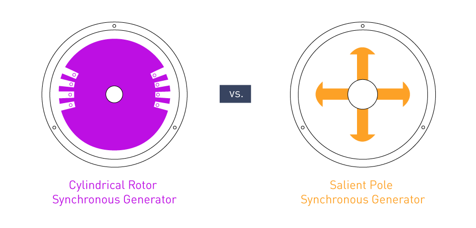
Figure 1: Cylindrical and Salient Pole Rotors
Excitation Methods: Slip rings or a brushless exciter can generate the rotor magnetic field in non-permanent magnet synchronous motors.
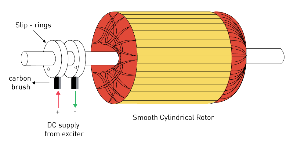
Figure 2: Slip Ring Providing DC Supply to Rotor
The method of excitation entails using a small alternating current generator with a field winding attached to the rotor. Installing a rectifier on the rotor shaft eliminates the need for slip rings and brushes by converting the generated alternating current (AC) into direct current (DC) for the motor's field winding.
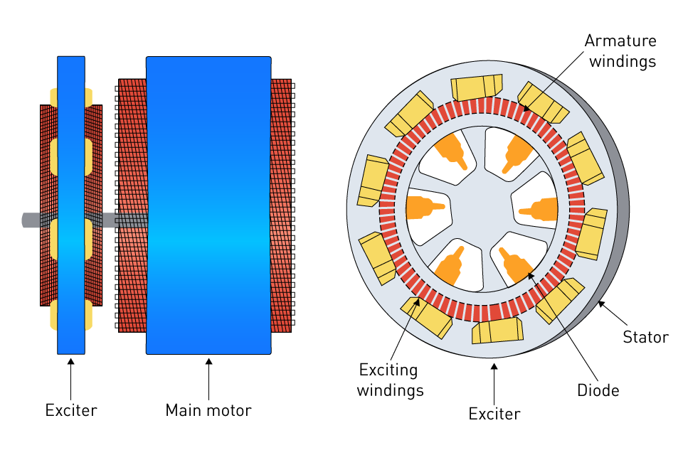
Figure 3: Exciter Method Providing DC Supply to Rotor
Operational Characteristics: Synchronous motors remain at a steady speed up to their full load once they have been started. This is one of their operational attributes. Because of their well-known ability to function effectively at high power levels and maintain a constant speed despite the presence of varying loads, they are ideal for applications that require precise speed control.
Synchronous Speed: Concept and Maintenance
Synchronous Speed Concept: The concept of synchronous speed is based on the fact that the supply frequency and the number of poles in a motor are the two factors that determine the synchronous speed of the motor.
$$N_s=\frac{120f}{P}$$Where Ns represents the synchronous speed in revolutions per minute (RPM), f is the supply frequency in hertz (Hz), and P represents the number of poles.
This relationship highlights the motor's ability to maintain a consistent speed, closely connected to the network's frequency.
Maintenance: To ensure consistent and dependable functioning, synchronous motors must undergo routine maintenance. This is particularly true for versions in which slip rings and brushes stimulate the rotor field. Maintenance responsibilities include evaluating and replacing worn brushes, ensuring that slide rings are clean and smooth, and monitoring the insulation that surrounds the rotor windings. Bearing lubrication and inspection, testing of the cooling system, and general mechanical integrity are the primary maintenance objectives for motors with permanent magnets or brushless exciters.
Synchronous motors find application in pumps, fans, compressors, and high-precision machinery due to their great efficiency and ability to operate at a constant speed regardless of the applied load. Motors are considered inductive devices because of their windings' inductivity. The phase of their current is falling behind the voltage, despite the fact that it is driven by an AC voltage source. Synchronous motors, on the other hand, have the capability to change their field current by modifying the rotor current. This causes the motor to appear as a capacitive load for the system, resulting in a leading rather than a lagging power factor. The versatility of these devices allows for power factor adjustment in industrial settings, thereby enhancing their usability. Synchronous motors are a great alternative for a wide variety of industrial applications because of their exact speed control, efficiency, and power factor adjustment capabilities. In comparison to induction motors, synchronous motors have a higher initial cost and are more complicated because of their complexity.


Induction Motors
Induction motors, also known as asynchronous motors, are known for their ease of use, dependability, and cost-effectiveness, making them the industry's workhorses.
Design Principles and Operational Mechanics
There are two primary components that make up the fundamental structure of an induction motor. These components are the stator and the rotor. A number of electrical windings or coils, contained in slots in a laminated core, construct the stator. The flow of alternating current (AC) through these windings creates a rotating magnetic field. The rotor, which is located inside the stator, is typically a cylindrical laminated core with conductive bars running along its length. Metal rings short-circuite these bars at each end, forming a cage-like structure known as a squirrel-cage rotor. An additional variety of rotor is referred to as a wound rotor. The wound rotor features three-phase windings evenly spaced 120 degrees apart, connected to slip rings established on the rotor shaft.
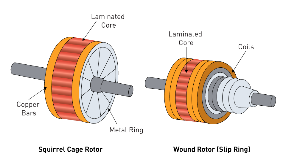
Figure 4: Squirrel Cage and Wound Rotor of Induction Motor
The interaction between the stator-produced magnetic field and the rotor-induced magnetic field controls the operation of an induction motor. This interaction produces electromagnetic torque, leading to the rotation of the rotor. The phenomenon known as slip happens when the rotor's rotational speed does not surpass the synchronous speed of the stator field.
Induction Process and Rotor Slip Phenomenon
As the magnetic field of the stator rotates, it causes a current to flow through the rotor. This current is caused by the relative motion that exists between the magnetic field and the rotor. This is the beginning of the induction process. According to Lenz's Law, the induced current in the rotor will flow in a direction that is opposite to the cause of its formation. This will result in the creation of the rotor's magnetic field, which will then interact with the field of the stator to produce motion.
Slip is a typical feature of induction motors, defined as the difference between the rotational speed of the magnetic field and the actual speed of the rotor, expressed as a percentage of the former. Slip is defined as the difference between the two speeds. Induction motors cannot produce torque without slip; without it, there would be no relative motion between the stator field and the rotor, and thus, there would be no induced current or torque. Slip is important for the production of torque.
$$s=\frac{\left(n_{S\ }-n_a\right)\cdot100%}{n_s}$$Where s is the slip, ns is the synchronous speed of the magnetic field, and na is the shaft rotating speed.
The slip is at its highest level while the rotor is not spinning. The slip varies between 1 - 5% percent depending on the horsepower of the motor, with higher-power motors often having less slip.
Linear Motors
Design
Linear motors, a type of induction motor, produce motion in a straight line instead of spinning. In essence, they "unroll" the conventional motor in order to generate linear force along a path. Two components make up the design: the primary component, which is comprised of windings, and the secondary component, which is comparable to the rotor in conventional motors and is typically a plate that is magnetically conductive and has a flat surface.
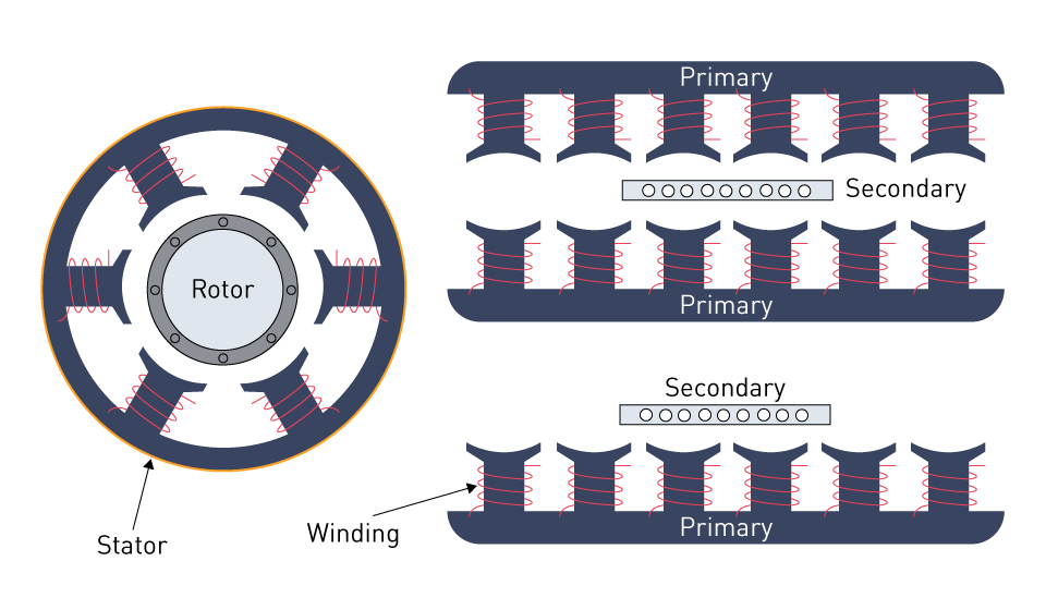
Figure 5: Comparison of Induction Motor and Linear Induction Motor Structure
Operational Characteristics
The operation of linear motors is similar to that of their rotary counterparts. The primary component generates a moving magnetic field, which in turn induces currents in the secondary component, which in turn provides the secondary component with the ability to move along the path. Because linear motors do not require mechanical transmission systems (such as gears and belts), they provide direct linear motion.
This results in enhanced efficiency, higher speeds, and improved control precision. Linear motors eliminate the need for mechanical transmission systems.
Because of their smooth functioning, high acceleration capabilities, and exact placement, linear motors find uses in a broad variety of fields, including transportation (maglev trains), manufacturing (assembly lines), and medical devices (MRI tables). These applications rely on the motors' ability to precisely position themselves.
Induction Motors: Performance and Efficiency
Many applications use induction motors because of their durability, ease of maintenance, and lack of brush requirement. Their efficiency and performance can vary depending on the specifics of their design, such as the number of poles, the quality of the materials, and the winding structure. Developments in inverter technology and variable-frequency drives have further expanded the versatility of induction motors. These advancements have made it possible to precisely adjust the speed of the motor in a variety of applications, as well as improve the motor's energy efficiency.
Performance and Efficiency Comparison
The landscape of alternating current (AC) motors contains a wide variety of designs, each of which offers distinctive performance characteristics as well as different levels of efficiency and maintenance requirements. This versatility makes it possible to modify the use of motor technology to meet the specific operational requirements of a wide range of industries. A comparative examination of synchronous and induction motors reveals their situational benefits, including linear variations, and guides the selection of these motors for specific applications.
Efficiency, Performance, and Maintenance Comparison
Efficiency: In terms of efficiency, synchronous motors are generally more efficient than induction motors, particularly when operating at greater power levels and maintaining a steady speed. Synchronous motors do not slip, which is why this phenomenon exists. On the other hand, developments in induction motor technology, specifically the incorporation of variable frequency drives (VFDs), have resulted in a significant improvement in their efficiency, particularly in applications that involve changing speed.
Performance: Synchronous motors' performance allows them to maintain a constant speed regardless of the applied load. This makes them perfect for applications that require precise speed control. In applications where torque variation with load is required, induction motors experience a slight change in speed due to slip. This feature could prove beneficial for applications that align with the specific requirements.
Maintenance: Induction motors often require less maintenance than synchronous motors. This is primarily because induction motors, unlike squirrel cage induction motors, do not include commutators or slip rings, components that require regular servicing. Synchronous motors may require more frequent maintenance.
They require more maintenance because of their more complicated rotor systems, particularly in designs that use slip rings for rotor excitation.
Situational Advantages and Typical Use Cases
Synchronous Motors: Synchronous motors are great for big industrial applications because of their ability to work at a constant speed and enhance power factor. Examples of such applications include pumps, fans, and compressors in manufacturing plants, chemical plants, and utility plants. Applications that require accurate speed control, like synchronous clocks, timers, and recording equipment, also opt for them. The aforementioned applications are included.
Induction Motors: Applications for induction motors range from small domestic appliances to large industrial operations due to their durability, low cost, and minimal maintenance requirements. Induction motors are widely employed because of these characteristics. When combined with variable-frequency drives (VFDs), they are especially well-suited for applications that involve variable speeds, such as those found in HVAC systems, electric vehicles, and conveyor belts. Because of their ease of use and dependability, induction motors have become an indispensable component in environments ranging from domestic to industrial.
Linear Motors: Linear motors produce direct linear motion, eliminating the need for mechanical connections. This eliminates the need for maintenance, thereby reducing maintenance time and enhancing both efficiency and precision. Applications that require high-speed linear movement and accurate placement, such as automated assembly lines, elevators, and maglev trains, are examples of the types of applications that include their utilization.
Strategies for Improving Efficiency and Reducing Losses
There are several ways to increase the power factor and efficiency of AC motors, which will ultimately lead to a decrease in energy consumption and operating expenses:
Power Factor Correction Capacitors: Installing capacitors in the motor circuit or power factor correction capacitors at the distribution panel can enhance the power factor of alternating current (AC) motors. Capacitors deliver reactive power locally to improve the power factor. As a result, the initial power source draws less reactive power.
Variable Frequency Drives (VFDs): As previously mentioned, VFDs can significantly enhance the efficiency of alternating current (AC) motors, especially in applications with variable loads. In specific operating situations, variable-frequency drives (VFDs) can reduce energy consumption and improve power factor. This is accomplished by precisely regulating the motor speed to match the load requirements.
High-Efficiency Motors: One straightforward method for enhancing both efficiency and power factor is to switch out regular motors for high-efficiency ones. High-efficiency motors, designed with enhanced materials and tighter production tolerances, minimize electrical and mechanical losses during the manufacturing process.
Load Management: Optimizing the load on the motor can enhance its efficiency and power factor. Operating motors at a capacity that is relatively close to their rated capacity results in the highest power factor and the highest efficiency. In order to improve the performance of motors, it is important to avoid under-loading or overloading them.
Regular Maintenance: It is possible to reduce mechanical losses and enhance efficiency by doing routine maintenance on motors. Maintenance includes keeping motors in optimal condition by performing regular inspections on bearings, alignment, and ventilation. Additionally, we can minimize electrical losses by ensuring the security of electrical connections and the prevention of insulation damage.
直接登录
创建新帐号