Component Selection and Sizing
Criteria and Impact on Performance
In LLC resonant converters, the selection of components and the sizing of those components are critical steps that have a significant impact on the overall performance and efficiency of the power conversion system. Within an LLC resonant converter, the resonant inductors, capacitors, and switching transistors are elements that are considered to be essential components.
It is the capacity of these components to manage the required power levels, frequency of operation, and thermal characteristics that serve as the selection criteria for these components. As an illustration, inductors and capacitors ought to be selected on the basis of their resonant frequencies, which ought to coincide with the frequency at which the LLC converter is intended to operate.
When selecting switching transistors, which are typically MOSFETs or IGBTs, the voltage rating, current-carrying capacity, and switching speed of the transistors are the most important factors to consider. Switching transistors that are faster can improve efficiency, but they also have the potential to increase electromagnetic interference (EMI), which is something that needs to be carefully considered.
For the purpose of preserving efficiency, minimizing losses, and ensuring the dependability of the power supply, it is essential to ensure that the components are sized appropriately. Having components that are too large can result in unnecessary costs and physical bulk, while having components that are too small can cause overheating, higher losses, and even the possibility of failure.
Optimization for Desired Outcomes
The optimization of component sizes in LLC converters involves striking a compromise between the goals of obtaining high efficiency, maintaining stable operation, and satisfying the limits of the application in terms of both monetary and physical dimensions.
As an illustration, maximizing the size of the resonant capacitor can have a direct impact on the efficiency of the converter as well as its capacity to maintain zero voltage switching (ZVS), which is essential for reducing switching losses.
In addition, the size of the inductor has an effect on the load range that the controller is able to maintain a high level of efficiency over. It is possible for an inductor that has been properly tuned to assure efficient performance across a wider range of loads, which in turn makes the power supply versatile for a variety of applications.
Simulations and modeling are vitally important in the process of selecting components and determining their sizes. With the help of sophisticated software tools, designers are able to fine-tune their designs in order to achieve the best possible results. These systems may do this by predicting how alternative component choices will affect performance under different operating situations.
When designing LLC converters, the ultimate objective is to choose and size components that not only conform to the technical criteria but also correspond with the economic and practical restrictions of the final product. This is the ultimate goal behind the design process.

Frequency Control and Modulation
Methods for Achieving Optimal Switching Frequencies
When it comes to LLC resonant converters, managing the switching frequency is essential to achieving the highest possible level of functional efficiency. The frequency control methods have a direct impact on the converter's performance within its resonance frequency, which is critical for maintaining high efficiency and reducing losses.
One popular method is to employ a variable-frequency control system, which alters the switching frequency based on the load conditions. This strategy enables the LLC converter to function at a frequency that is relatively close to its resonant frequency, thereby maximizing its efficiency under a wide range of load situations.
The implementation of phase-shift modulation is still another way. This method entails varying the phase difference between the driving signals of the switches. This modulation technique allows precise control over the power passing through the resonant tank circuit, ultimately optimizing the converter's performance.
Another method to achieve frequency modulation is to use pulse-width modulation (PWM), which involves varying the duty cycle of the switching signals. Despite its common use in non-resonant converters, resonant applications can adapt this technique to control the power flow.
In contemporary LLC converters, digital control approaches, which may include the incorporation of microcontrollers or digital signal processors (DSPs), are becoming increasingly prevalent. These enable a higher level of precision and adaptability in frequency management by enabling complex control algorithms that can dynamically modify the frequency in response to real-time feedback.
Impacts on Efficiency and Reliability
The frequency management and modulation approaches selected before the converter's manufacture significantly influence its efficiency and dependability. Optimizing the switching frequency allows the converter to operate at its lowest loss point, leading to immediate efficiency gains. Operating at or near the resonant frequency reduces switching losses and component stress, thereby enhancing the converter's reliability and prolonging its lifespan. It is especially important to keep this in mind when dealing with high-power applications, which might experience severe thermal and electrical stressors.
It is also vital to have accurate frequency management in order to prevent operational issues related to the converter, such as sub-harmonic oscillations or over-stressing the components. The converter may encounter these issues if it operates beyond its intended frequency range. Furthermore, effective frequency modulation is responsible for superior electromagnetic interference (EMI) performance. It is essential for designers to limit electromagnetic emissions in order to comply with electromagnetic compatibility (EMC) regulations. Carefully managing the frequency and its harmonics can accomplish this.
An additional factor contributing to increased reliability is the maintenance of consistent operation within the power semiconductor's safe operating area (SOA). The significance of this cannot be overstated in situations where the load conditions might be subject to substantial variations, such as in industrial applications.
A thoughtfully built frequency control mechanism enables the LLC converter to adjust to varying operational conditions without sacrificing efficiency or putting the components in danger of damage. This versatility is critical in applications with dynamic loads or constantly changing input conditions.
Stability and Feedback Control
Ensuring Robust and Stable Operation
In order for LLC converters to function in a dependable and effective manner, stability is absolutely necessary. An unstable system can result in oscillations, poor power management, and possibly destructive stress on components, which can also lead to more erratic behavior. The designers of the controller need to carefully examine the feedback loop in order to guarantee the controller's stability. The phase margin and gain margin of the system are also subject to scrutiny as part of this process. This margin serves as a signal of how near the system is to becoming unstable, and it is an essential component in the design of the feedback loop.
The creation of a Bode plot, which is a graphical depiction of the system's frequency response of the system, is a common step in the process of stability analysis. Having this knowledge is beneficial in understanding how the system reacts to different frequencies, particularly in the vicinity of the LLC circuit's resonant frequency.
The design of the compensation network within the feedback loop is an essential component for ensuring stability. This network, typically composed of capacitors and resistors, shapes the frequency response of the system. This network is designed to ensure that the system is stable across the entire operating range.
Techniques for Feedback Implementation
A combination of hardware and software solutions is required in order to successfully implement feedback in LLC converters. In most cases, the feedback mechanism is made up of sensors that measure voltage and current, a controller that is responsible for processing the feedback data, and at least one compensation network. When it comes to monitoring the output of the converter in real time, voltage and current sensors are extremely important components. These sensors provide the necessary feedback for the control loop, allowing it to dynamically modify the operation to maintain stability.
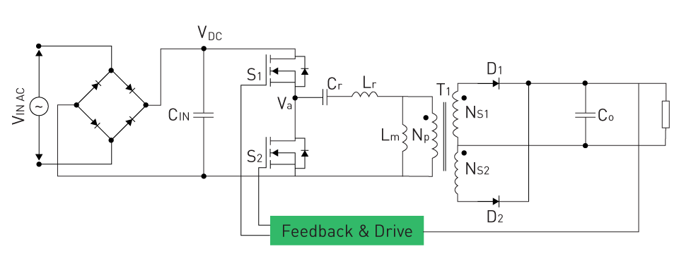
Figure 1: Half-Bridge LLC Converter with Control Loop
Contemporary LLC controllers frequently utilize DSPs, also known as microcontrollers, to process feedback signals. Furthermore, in comparison to conventional analog controllers, these processors are capable of implementing complicated control algorithms, which results in increased precision and adaptability.
Advanced techniques like digital control loops enable the use of more sophisticated feedback mechanisms. Adaptive control techniques are one example of this. These strategies dynamically modify parameters based on the operating conditions, which further improves the LLC converter's stability and performance.
In addition to providing feedback on the output voltage and current, modern LLC converters may also provide feedback on temperature, variations in input voltage, and changes in load. The utilization of this multi-faceted feedback system guarantees comprehensive monitoring and control, which ultimately results in a power conversion process that is both extremely stable and very efficient.
Thermal Management and Layout Considerations
Addressing Thermal Concerns in Design
When designing LLC converters, thermal management is an essential component because it has a direct impact on both the converters' performance and dependability. Excess heat can cause component degradation, which can have a negative impact on the converter's longevity and efficiency. A variety of components, particularly power semiconductors and magnetic components like inductors, produce substantial amounts of heat during operation, necessitating consideration in the design process.
The selection of components that have appropriate thermal characteristics and the utilization of materials that aid in heat dissipation, such as thermal interface materials and heat sinks, are the first steps in the process of effective thermal management. Active cooling solutions like fans or liquid cooling can enhance heat dissipation when passive cooling methods like heat sinks and natural convection prove inadequate.
Thermal modeling and simulation are critical during the design process because they allow designers to make accurate predictions about the thermal behavior of the system under a variety of operating conditions and structure configurations. This predictive technique assists in identifying potential hot spots and devising mitigation strategies before finalizing the design.
Optimal Layout for Heat Dissipation
The physical architecture of the components within an LLC converter significantly influences its capacity to disperse heat adequately. In order to get the best possible thermal performance, it is vital to strategically position these heat-generating components. It is essential to ensure that there is sufficient distance between components in order to promote air flow and heat distribution. Layouts that are too congested can result in hot spots and a reduction in the efficiency with which heat is dissipated.
When it comes to thermal management, the orientation of components is also an important factor. For example, putting components in a vertical orientation may occasionally be helpful in increasing convective cooling. It is possible to ensure that heat is distributed evenly over the board by utilizing materials that are thermally conductive but electrically insulating. This will help to minimize localized overheating. Another key aspect to take into account is the positioning of thermal management components, such as heat sinks, in relation to heat sources. In order to achieve the highest potential level of heat transfer efficiency, the thermal channel that connects the heat source to the heat sink ought to be as direct as possible.
When it comes to high-power applications, the utilization of a thermal interface material (TIM) between the component that generates heat and the heat sink has the potential to significantly enhance thermal conductivity and decrease thermal resistance.
直接登录
创建新帐号