Voltage
One of the most popular ways for sensors to exchange information is through voltage output. This form of output is flexible for a wide range of sensors since it frequently responds proportionately to changes in the measurand, or the quantity being measured.
Common Types and Their Principles
Piezoelectric Sensors: These work on the basis of the piezoelectric phenomenon, which states that when a material experiences stress, it will generate a voltage. Piezoelectric materials, such as quartz or certain ceramics, produce a voltage in reaction to mechanical strain and are frequently employed in accelerometers, microphones, and specific kinds of pressure sensors. Their ability to sense dynamic changes, particularly fast movements or vibrations, is what makes them perfect.
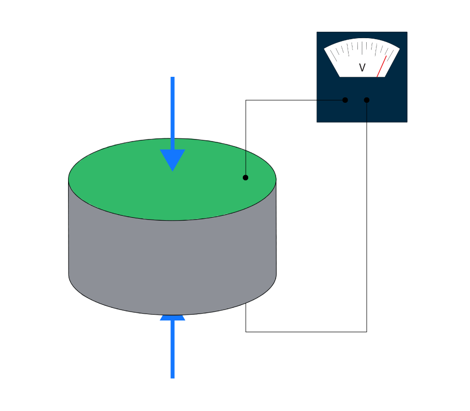
Figure 1: Piezoelectric Disk
Photovoltaic Sensors: Voltage is produced by these sensors from light energy. When photovoltaic or solar cells are exposed to light, they produce a voltage. These cells are commonly built of semiconductor materials like silicon. The light intensity determines how much voltage is generated. When there is sufficient light, they are commonly utilized as power sources or in light intensity measurement.
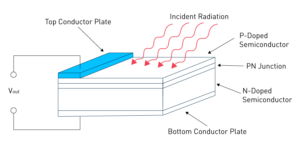
Figure 2: Photovoltaic Cell
Other voltage-based sensors exist, each with a different basis of operation; examples include thermocouples, which produce voltage in response to temperature variations, and Hall effect sensors, which provide voltage outputs when magnetic fields are present.
Impact of Load Impedance on Voltage-Based Sensors
The load's impedance can have a big impact on voltage-output sensors' overall performance. The load's (often an amplifier or measuring equipment) input impedance needs to be significantly higher than the sensor's output impedance in order for the sensor to function at its best.
A voltage divider can occur when the load impedance is too low in relation to the output impedance of the sensor. This lowers the output voltage of the sensor and leads to measurement inaccuracies. Furthermore, especially for sensors that detect characteristics changing quickly, the dynamic response of the sensor may be impacted, resulting in delays or distortions in the signal.
Since piezoelectric sensors have a high internal impedance, it is desirable to link them with amplifiers that have a high impedance to avoid signal attenuation. The efficiency and linearity of energy conversion for photovoltaic sensors can differ depending on the connected load, even though they can operate with a range of load impedances.
In actual application, it is important to take care while designing and choosing the interface electronics to make sure that the impedance characteristics meet the needs of the voltage-output sensor being utilized.


Current
A direct and linear relationship between the detected parameter and the current is frequently provided by current-output sensors, which work by generating a current signal that varies in relation to the measurand. A current signal has the benefit of being less vulnerable to outside noise or interference due to its nature, particularly over lengthy cable lines.
How Current Outputs are Generated
Photodiode in Photoconductive Mode: Semiconductor devices called photodiodes, generate electricity in response to light. A reverse-biased photodiode is one that receives a voltage provided in the opposite direction of the forward-bias direction of the diode when it is operating in the photoconductive mode. In these circumstances, electron-hole pairs are produced when photons strike the diode. These carriers are accelerated by the reverse bias, producing a photocurrent that is proportionate to the amount of light. The photoconductive mode can respond more quickly than the photovoltaic mode, but it may also produce more noise.
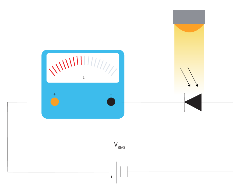
Figure 3: Photodiode
Other techniques for producing current outputs include:
Transistor-Based Sensors: These make use of transistors' intrinsic characteristics. A transistor's current can vary under specific circumstances, and this variation might be related to the amount being measured.
Electrochemical Sensors: These sensors, which are frequently used to detect gases, generate electricity when a particular chemical reaction occurs at an electrode.
Importance of Load Conditions
A sensor's current output is usually meant to pass through a load resistance that is known already, over which a voltage corresponding to the current will grow. The sensor's performance can be greatly impacted by the type of load.
Load Resistance: The selection of load resistance is essential. Non-linearity, a narrower signal range, or saturation might result from a mismatch. For example, a voltage range of 1V to 5V will be produced by a 4mA to 20 mA current loop sensor intended to function across a 250-ohm load. This voltage range will vary if a different load resistance is used.
Grounding and Shielding: In order to prevent ground loops, which might inject undesired noise into the current signal, proper grounding is necessary. Shielding may also be required to shield the transmission from outside electromagnetic interference.
Cable Length: One benefit of current-output sensors, such as the 4-20 mA system, is that the signal resists voltage changes across the cable over extended cable lengths. On the other hand, very long cables may introduce capacitance, which may reduce the bandwidth of the signal.
Current-output sensors provide benefits over distance and noise immunity, but it's critical to make sure the circumstances and interface electronics match the sensor's requirements and intended use.
Remember: It's not just about getting accurate readings when the load criteria are satisfied; it's also about making sure the sensor lasts as long as possible and performs at its best during that time.
Resistance
Resistance-based sensors work on the basis of electrical resistance changing in response to changes in a certain physical or environmental characteristic. A proper interface circuit is frequently required to convert a physical parameter that changes in resistance into an electrical signal that can be understood.
Variable-Resistance Sensors
Thermistors: Thermistors are semiconductor-based, temperature-sensitive resistors. The temperature greatly affects their resistance. Positive temperature coefficient (PTC) and negative temperature coefficient (NTC) are the two main types of thermistors. As the temperature rises, PTC thermistors exhibit an increase in resistance, whereas NTC thermistors exhibit a drop in resistance. Due to its great sensitivity, thermistors are frequently employed in applications that call for accurate temperature readings within a constrained temperature range.
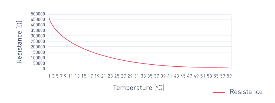
Figure 4: Resistance vs. Temperature for an NTC Thermistor
Resistance Temperature Detectors (RTDs): Precision temperature sensors, or RTDs, are composed of a metallic element. The element's metal of choice—platinum, nickel, or copper—usually depends on the needs of the application, and more especially, on the sensor input of the instrument. RTDs are highly accurate and predictable over a broad temperature range since their resistance rises linearly with temperature. Since long-term stability is essential in industrial and scientific applications, resistor-thermistors (RTDs) are utilized instead of thermistors because of their almost linear resistance-temperature connection.
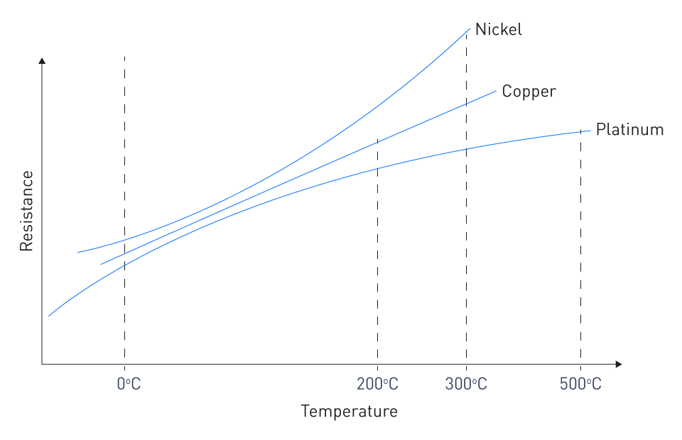
Figure 5: Resistance vs. Temperature for Different Types of RTDs
Additional sensors with changing resistance are photoresistors, whose resistance varies with light intensity, and strain gauges, whose resistance changes under mechanical force.
Impact of Excitation Voltage/Current
Self-Heating: An application of voltage or current to a resistance-based sensor causes power dissipation, which in turn causes the sensor to overheat. If not appropriately controlled, this self-heating of temperature sensors, such as thermistors and RTDs, can lead to inaccurate readings. Excitation currents should therefore be kept to a minimum.
Signal-to-Noise Ratio (SNR): The SNR may be impacted by the magnitude of the excitation voltage or current. Larger signals may result from increased excitation, but noise levels may also rise—particularly in areas where electromagnetic interference is present.
Linearity: The linearity of the sensor's output can depend on the type of stimulation used. At specific excitation levels, some sensors may exhibit more linear behavior.
Bridge Circuits: In Wheatstone bridge circuits, where a change in resistance results in an imbalance and a quantifiable voltage difference, resistance sensors are frequently used. In order to determine the sensor's sensitivity and output range, the excitation voltage given to such a bridge is crucial.
In conclusion, resistance-based sensors provide a dependable way to measure different parameters; nevertheless, in order to guarantee accuracy, stability, and best performance, significant thought needs to be given to the excitation source.
Frequency
A signal with an output frequency that is frequently proportional to the measured physical parameter's magnitude is produced by frequency-based sensors. In particular, these sensors can provide stability and noise immunity that set them apart from other output kinds.
Oscillatory Sensors and Frequency Modulation Techniques
Oscillatory Sensors: Either an external input can cause these sensors to oscillate, or they can oscillate naturally. One example of an external influence that can alter the natural resonant frequency is temperature or pressure in quartz crystal resonators. The amount of the physical change can be estimated by measuring the frequency shift brought about by the external stimulus.
Frequency Modulation Techniques: It's possible that sensors don't always produce a frequency output natively. In these situations, the primary output of the sensor (such as voltage or resistance) can be modulated in a variety of ways to produce a frequency signal. A popular technique is frequency modulation (FM), which modifies a carrier wave's frequency based on the output of the sensor. Electronic circuits often employed for this purpose include voltage-to-frequency converters and voltage controller oscillators (VCOs) in phase-locked loops (PLLs).
Frequency-Based Measurement Advantages
High Immunity to Offset and Drift: Compared to analog signals, a signal's frequency is less susceptible to offset errors and long-term drift. The problems associated with DC offset are naturally reduced because frequency has no DC component.
Robustness to Noise: A signal's frequency, particularly in digital systems, is very resistant to noise based on amplitude. The signal frequency remains unaffected by the noise, but the signal amplitude is. This guarantees that even in electrically loud surroundings, the transmitted signal quality will not change.
High Resolution and Precision: When using high-quality oscillators, frequency-based measurements can have incredibly high precision.
For many sensing applications, frequency-based sensors and the modulation techniques that go along with them offer a reliable option, particularly where high precision and noise immunity are needed. Simple analog sensors may have a simpler initial setup, but the long-term advantages in accuracy and dependability frequently outweigh the additional complexity.
直接登录
创建新帐号