Strain Gauges
One of the basic transducers used in the measurement of mechanical quantities is the strain gauge. The sensitivity of a material's electrical resistance to mechanical deformation is fundamental to how it functions.

Figure 1: Strain Gauge
Working Principle: Resistive Change Due to Deformation
The connection between mechanical strain and resistivity is the fundamental idea underlying a strain gauge. The strain gauge's electrical resistance varies as it experiences mechanical stress, which causes it to stretch or compress. More specifically, resistance tends to decrease with compression and to rise with elongation. Strain gauges are a useful instrument for measuring mechanical stress since the degree of resistance change is directly proportional to the applied strain.
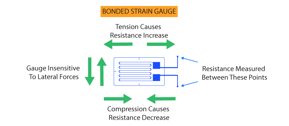
Figure 2: Strain Gauge Operation
Materials: Metallic Foil and Semiconductor
Metallic Foil: These strain gauges are the most often used kind. They are made of thin, grid-patterned metallic wire or foil. A flexible backing material is fused to the foil and subsequently fastened to the test item. The metallic foil deforms together with the item, changing its electrical resistance in the process.
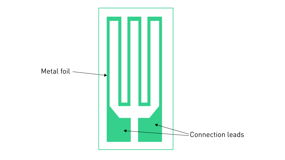
Figure 3: Metallic Foil Strain Gauge
Semiconductor: Compared to their metallic equivalents, semiconductor strain gauges, which are composed of silicon or germanium, are usually far more sensitive. In semiconductors, the piezoresistive effect results in a noticeable shift in resistance with deformation. However, because of their non-linear behavior, they can be more difficult to interface with and more sensitive to temperature changes.
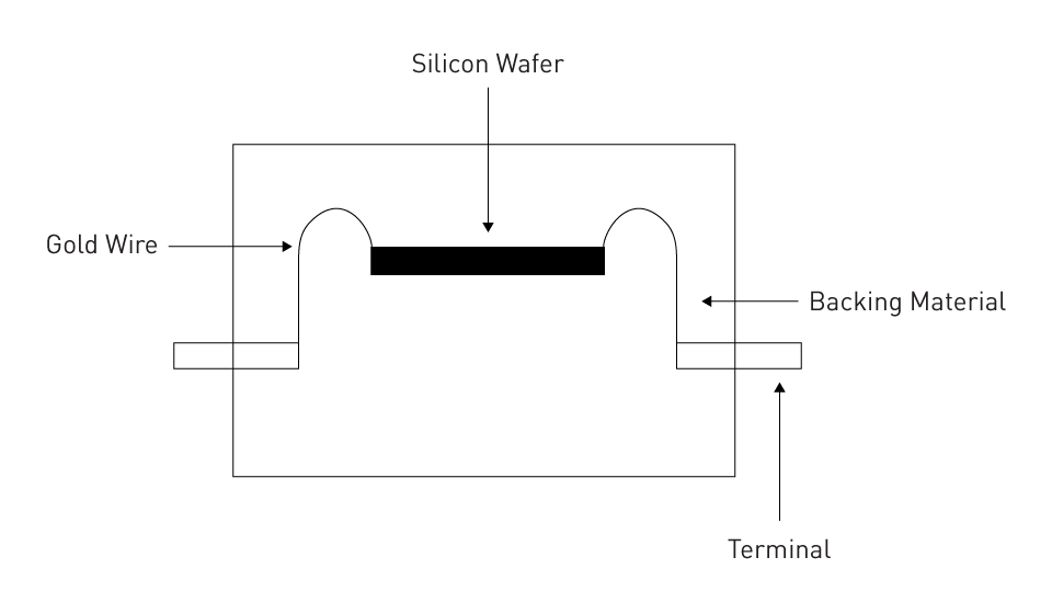
Figure 4: Semiconductor Strain Gauge
Wheatstone Bridge Circuitry and Signal Conditioning
It can be challenging to measure the raw signal from a strain gauge directly since it is essentially a little change in resistance. As a result, a Wheatstone bridge circuit usually incorporates it. The strain gauge is one of the four resistors in this design. A noticeable voltage difference results from an imbalance in the bridge caused by strain on the gauge's resistance.
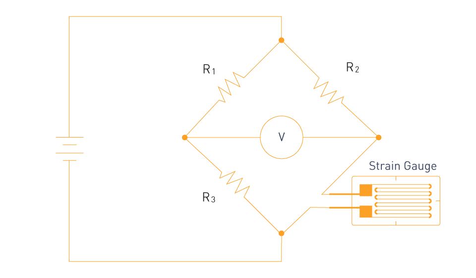
Figure 5: Measurement using Strain Gauge
Signal conditioning techniques are used to further improve the accuracy and quality of the signal. Amplification increases the signal's strength, which makes it appropriate for direct reading or digital conversion. Noise reduction guarantees that the measured strain is free from outside interference, and is frequently accomplished by filtering.
Applications: Structural Health Monitoring and Load Cells
Structural Health Monitoring: In the field of civil engineering, strain gauges are essential for evaluating the structural soundness and integrity of buildings, bridges, and dams. Engineers can monitor stress distribution and identify possible areas of concern by carefully putting strain gauges on different regions of a structure.
Load Cells: These are instruments meant to measure load or force. Strain gauges detect how a metal component—typically a beam or column—deforms inside a load cell in response to an applied force. After that, an electrical signal corresponding to the applied force is created from this deformation.
Strain gauges are essential in the field of mechanical sensors because they provide accurate and dependable measures of mechanical stress, which are important for both industrial and scientific applications.
Piezoelectric Sensors
By using an intriguing property of some materials, piezoelectric sensors are able to directly bridge the gap between the mechanical and electrical domains by converting mechanical stress into electrical energy. These sensors are used in a wide range of applications, from everyday objects to sophisticated industrial machinery.
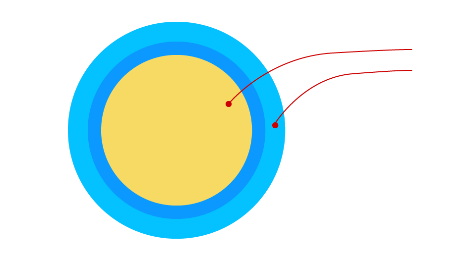
Figure 6: Piezoelectric Sensor
Working Principle: Voltage Generation from Mechanical Stress
The Greek word "piezein," which means to press or squeeze, is where the phrase "piezoelectric" comes from. The capacity of some materials to produce an electric charge in response to applied mechanical stress is the fundamental phenomena of piezoelectricity. On the other hand, these materials distort mechanically when exposed to an electric field.
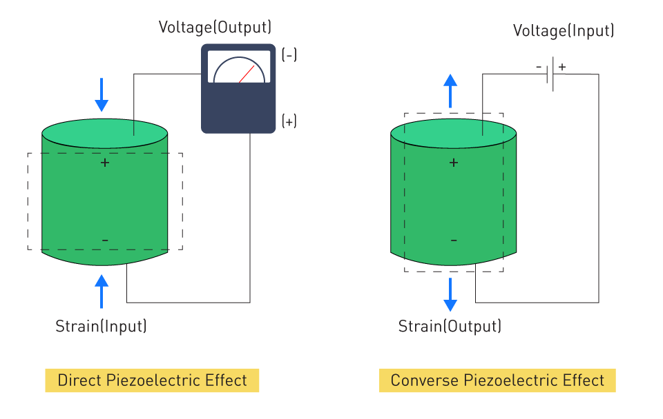
Figure 7: Direct and Converse Piezo Effect
Positive and negative charge centers in the material shift in response to mechanical stress, creating an external electric field that causes charge generation. Piezoelectric sensors are very useful for dynamic measurements since the amount of this voltage is directly proportional to the mechanical stress exerted.
Materials: Quartz and PZT (Lead Zirconate Titanate)
Quartz: One of the first materials to be found with piezoelectric capabilities is quartz, a naturally occurring substance. It is the material of choice for precision applications such as crystal oscillators in electrical circuits because of its exceptional temperature stability, frequency stability, and resilience to high pressures.
PZT (Lead Zirconate Titanate): Man-made ceramic PZT is renowned for being extremely sensitive due to its high piezoelectric coefficient. Owing to its exceptional characteristics, PZT has emerged as the most widely utilized piezoelectric substance in diverse sensors and actuators.
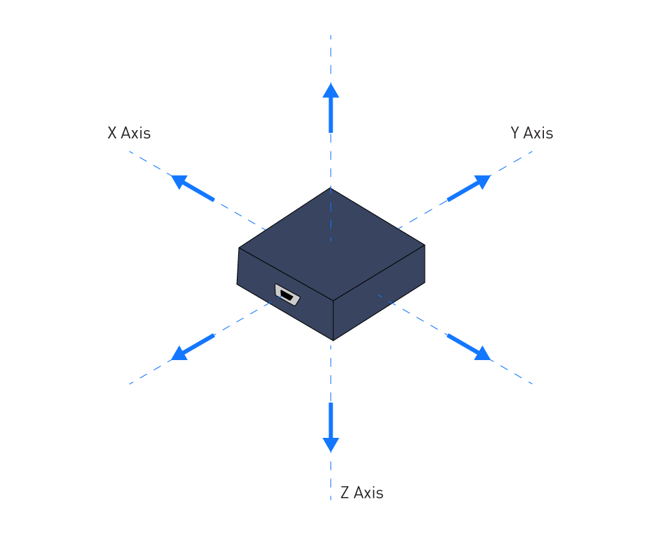
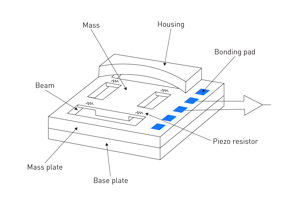
Vibration Monitoring: Since piezoelectric sensors are good at investigating dynamic shifts, they are a great tool for tracking vibrations in systems, machinery, and buildings. For predictive maintenance and system improvement, they can offer comprehensive information on the vibrations' magnitude, frequency, and phase. Acoustic Sensing: Many ultrasonic sensors and microphones are based on the piezoelectric concept. A proportionate voltage is produced by sound waves, which are a type of mechanical vibration, striking the sensor. For a variety of acoustic applications, such as underwater sonar, medical imaging, and contactless distance measurements, piezoelectric sensors are therefore a great option. Conclusively, piezoelectric sensors are an essential component of the sensor world because they effortlessly and precisely bridge the gap between mechanical phenomena and electrical analysis through the direct conversion of mechanical stress to voltage. Accelerometers are mechanical sensors that have made a name for themselves by measuring dynamic motions including acceleration, vibrations, and gravitational force. Because of these sensors' portability, accuracy, and compact size, they can be found in a wide range of products, including spacecraft and cellphones. Figure 8: Accelerometer Newton's second law of motion forms the basis of an accelerometer's basic operation: An object experiences displacement as it accelerates because of a force applied to its mass. This displacement is measured by accelerometers and translated into an electrical signal proportional to the applied acceleration. A seismic mass, also known as a proof mass, is the core of the accelerometer. It is fixed to the sensor housing by a mechanical suspension mechanism. The seismic mass's inertia causes the sensor to shift in relation to the housing when it encounters acceleration. An electrical signal is generated after this displacement is noticed. Figure 9: Seismic Accelerometer Accelerometer design has been transformed by Micro-Electro-Mechanical Systems (MEMS) technology, which makes it possible to reduce mechanical systems to micron-scale structures on semiconductor chips. Capacitive MEMS Accelerometers: The capacitance between two plates fluctuates inversely with their distance from one another, which is the basis for how these accelerometers operate. One plate is formed by the seismic mass, while the other is formed by a fixed plate that is next to it. The spacing between the plates varies as the seismic mass moves in response to acceleration, changing capacitance. It is possible to quantify this shift and link it to the acceleration. Figure 10: Capacitive MEMS Accelerometer Piezoresistive MEMS Accelerometers: The resistance of embedded piezoresistive materials in these devices is influenced by the displacement of the seismic mass. The piezoresistive elements experience stress as the seismic mass shifts, which modifies the elements' resistance. An output voltage proportionate to the applied acceleration is subsequently obtained by translating this change in resistance. Figure 11: Piezoresistive MEMS Accelerometer Mobile Devices: Smartphones and tablets' auto-rotation capability is largely dependent on accelerometers. They enable the screen's display to adjust in accordance with the orientation of the device with respect to Earth's gravity. Vehicle Dynamics: Utilized in cars for airbag deployment, stability control, and other safety features. They are able to identify sudden braking or tilts, which could lead to crashes or rollovers. Seismic Sensing: Accelerometers can record seismic waves for the purpose of detecting and monitoring earthquakes. This provides important information for early warning systems and geological study. Research methods, safety systems, and technology have all advanced significantly because to accelerometers. It is anticipated that their integration into commonplace electronics and essential systems would further increase as improvements continue.Applications: Vibration Monitoring and Acoustic Sensing
Accelerometers
Working Principle: Inertia-Based Displacement Detection

MEMS Accelerometers: Capacitive and Piezoresistive Types

Applications: Mobile Devices, Vehicle Dynamics, and Seismic Sensing


直接登录
创建新帐号