Case Study 1: Analog Control in Power Supplies
An essential component of power electronics is analog control of power supplies, which guarantees steady and reliable power delivery to electronic systems. This case study examines how analog control is used in power supplies design and operation, with an emphasis on efficiency optimization, noise reduction, and voltage regulation.
To provide the required DC voltage and current from an AC mains supply or another DC source, power supplies are crucial components of electronic devices. In order to ensure that the power supply satisfies the demanding specifications of modern electronic systems, analog control techniques are frequently used to manage transient responses, lower noise, and regulate the output voltage.
Key Components and Design Principles
Voltage Regulation:
Linear Regulators: A pass transistor and an error amplifier are used by linear regulators, like the 7805 series, to maintain the output voltage constant. The error amplifier modifies the pass transistor to control the output after comparing it to a reference voltage.
Shunt Regulators: Simple voltage control is provided by shunt regulators, such as Zener diodes, which shunt excess current to maintain a steady voltage across the load.
Switch-Mode Power Supplies (SMPS):
Principle: High-frequency switching is used by SMPS to effectively transform electrical power. In order to keep the output voltage steady, analog control circuits adjust the duty cycle and switching frequency.
Components:
- PWM Controller: Generates pulse width modulation (PWM) signals to regulate the switching transistors.
- Error Amplifier: Adjusts the PWM duty cycle by comparing the output's feedback signal with a reference voltage.
- Feedback Loop: Provides negative feedback to the error amplifier, ensuring stability and rapid transient response.
Noise Reduction:
Filtering: To attenuate noise and ripple in the output voltage, capacitors and inductors are employed in low-pass, high-pass, and band-pass filter configurations.
Grounding and Shielding: To reduce electromagnetic interference (EMI) and guarantee clean power transmission, appropriate grounding and shielding procedures are used.
Design Example: 5V Linear Power Supply
System Requirements:
Input Voltage: 9V to 12V DC
Output Voltage: 5V DC
Load Current: Up to 1A
Ripple Voltage: Less than 10mV
Design Components:
Voltage Regulator IC: 7805 linear regulator
Input Capacitor: 100µF electrolytic capacitor to filter the input voltage
Bypass Capacitor: 0.1µF ceramic capacitor for high-frequency noise reduction
Diodes: To indicate status of supply input and output.
Design Steps:
Step 1: Input Filtering: To filter out input voltage variations, place a 100µF capacitor across the input terminals.
Step 2: Voltage Regulation: Connect the 7805 voltage regulator IC with the output pin to the load, the ground pin to the common ground, and the input pin to the filtered input voltage.
Step 3: High-Frequency Noise Reduction: To eliminate high-frequency noise, connect the 0.1µF capacitor across the output terminals.
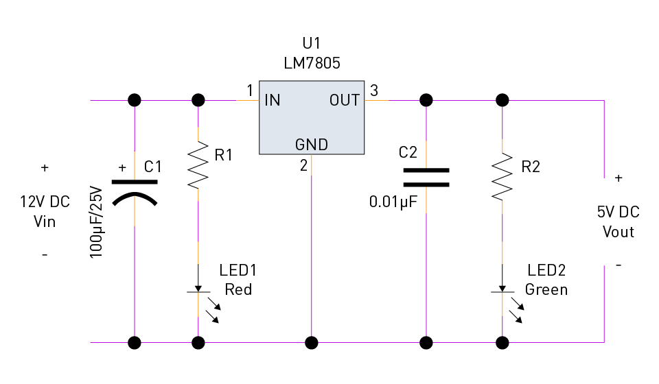
Figure 18: 5V power supply
Testing and Performance Evaluation:
Load Regulation: To make sure the output voltage stays within the specified range, measure it under varying load conditions.
Line Regulation: Check the stability of the output voltage as the input voltage varies.
Ripple and Noise: Make sure the output voltage is below the specified 10mV by measuring the noise and ripple with an oscilloscope.
Advanced Example: Switching Power Supply with PWM Control
System Requirements:
Input Voltage: 100V to 240V AC
Output Voltage: 12V DC
Load Current: Up to 5A
Efficiency: Greater than 85%
Design Components:
PWM Controller IC: TL494 or similar
MOSFET Switch: IRF540 or similar
Inductor: Custom-wound to handle the desired current and frequency
Output Capacitors: Low-ESR capacitors to minimize ripple
Feedback Network: Resistors and capacitors to provide feedback to the error amplifier
Design Steps:
Step 1: Rectification and Filtering: To filter out high-frequency noise and convert the AC input to DC, use a bridge rectifier and bulk capacitors.
Step 2: PWM Generation: To generate the required PWM signals, configure the TL494 PWM controller. To drive the MOSFET switch's gate, connect the output.
Step 3: Inductor and Capacitor Selection: Design the LC filter so that the switching output is smoothed and the DC output remains stable.
Step 4: Feedback Control: To control the duty cycle, implement a feedback loop from the output to the PWM controller's error amplifier input.
Testing and Performance Evaluation:
Efficiency Measurement: To calculate efficiency, measure input and output power, aiming for greater than 85%.
Load Testing: To guarantee stable operation, evaluate performance under varying load conditions.
Thermal Performance: To make sure the MOSFET and other components stay within safe operating temperatures, evaluate their thermal performance.
Case Study 2: Analog Controllers in Motor Drives
With their ability to precisely control motor speed, torque, and position, motor drives are crucial in a wide range of commercial and industrial applications. In motor drives, analog controllers are essential because they provide continuous, real-time control, which is crucial for applications requiring great responsiveness and reliability. With an emphasis on design strategies, practical applications, and underlying principles, this case study investigates the use of analog controllers in motor drives.
Motor drives transform electrical energy into mechanical energy, and accurate and efficient operation requires precise control. The ability of analog control systems to provide continuous, smooth control without the latency of digital systems makes them especially well-suited for motor drives. DC, induction, and brushless DC (BLDC) motors are among the common motor types utilized with analog controls.
Key Components and Control Strategies
Operational Amplifiers (Op-Amps):
Function: Op-amps drive power transistors or other switching devices and amplify error signals in feedback control loops.
Application: Crucial for implementing proportional-integral-derivative (PID) control algorithms, which are frequently employed in motor control.
Sensors:
Function: Give feedback on the motor's current, position, or speed.
Types:
- Tachometers: Calculate the speed of rotation.
- Encoders: Give accurate position feedback.
- Current Sensors: To manage torque, monitor motor current.
Power Transistors:
Function: Modulate or switch the motor's power supply.
Types: Insulated Gate Bipolar Transistor (IGBT), Metal-Oxide-Semiconductor Field-Effect Transistor (MOSFET), and Bipolar Junction Transistor (BJT).
Control Techniques
Proportional-Integral-Derivative (PID) Control:
Principle: minimizes the discrepancy between the desired setpoint and the actual motor speed or position by combining proportional, integral, and derivative actions.
Components:
- Proportional Control: Offers a prompt response to errors.
- Integral Control: Removes steady-state error.
- Derivative Control: Based on the rate of change, forecasts future errors.
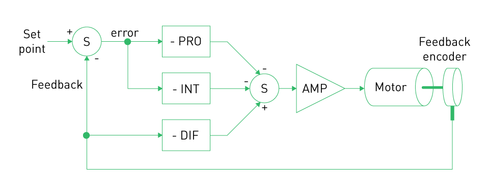
Figure 19: PID for motor position control
Hysteresis Control:
Principle: Robustly controls current by switching the motor drive state using a hysteresis band.
Application: Frequently used in BLDC motor drives, where accurate current control is essential.
Linear Current Control:
Principle: Controls the motor's current directly, guaranteeing precise torque control and smooth operation.
Application: Often utilized in servo motor applications that require precise torque control.
Design Example: DC Motor Speed Controller
System Requirements:
Motor Type: DC motor
Speed Range: 0 to 3000 RPM
Control Accuracy: ±1%
Load Conditions: Varying load torque
Components:
Op-Amps: LM324 for implementing the PID controller
Speed Sensor: Optical encoder for feedback
Power Transistor: MOSFET (IRF540) for switching
Resistors and Capacitors: Various values for tuning the PID controller
Design Steps:
Speed Sensing: Create pulses that match the motor speed using the optical encoder.
Error Signal Generation: To generate an error signal, use an op-amp to compare the desired speed (setpoint) with the actual speed.
PID Control Implementation: Depending on the error signal, configure the op-amps to provide derivative, integral, and proportional control.
Power Modulation: To regulate the voltage applied to the motor, use the PID controller's output to drive the MOSFET's gate.
Feedback Loop: Maintain a closed-loop system by constantly monitoring the motor speed and modifying the control signal as necessary.
Testing and Tuning:
Prototype: Connect the circuit to the DC motor after building it on a breadboard.
Tuning: To get the desired speed control accuracy and response, modify the PID settings (proportional gain, integral time, and derivative time).
Load Testing: To ensure stability and resilience, evaluate performance under various load conditions.
Advanced Example: Brushless DC Motor (BLDC) Controller
System Requirements:
Motor Type: BLDC motor
Speed Range: 0 to 5000 RPM
Torque Control: Precise torque regulation
Efficiency: High efficiency for battery-powered applications
Components:
Microcontroller: For generating PWM signals
Op-Amps: For implementing hysteresis control
Current Sensors: Hall effect sensors for feedback
MOSFETs: High-speed switching devices
Gate Drivers: To drive the MOSFETs
Design Steps:
Current Sensing: Measure the BLDC motor's phase currents using Hall effect sensors.
Error Signal Generation: Op-amps are used to generate an error signal by comparing the measured current with the desired current.
Hysteresis Control Implementation: To implement hysteresis control, configure op-amps to switch MOSFETs to maintain the current in the hysteresis band.
PWM Generation: To provide precise control over motor speed and torque, use the microcontroller to generate PWM signals based on the control input.
Feedback Loop: For steady and efficient working make sure the motor current is continuously monitored and adjusted.
Testing and Optimization:
Prototype: Connect the circuit to the BLDC motor after assembling it on a PCB or breadboard.
Tuning: To maximize performance, fine-tune the control parameters and hysteresis band.
Efficiency Testing: To ensure high efficiency, measure the thermal performance and power consumption under various operating conditions.
Case Study 3: Application in Renewable Energy Systems
For sustainable energy production, renewable energy sources like solar and wind power are crucial. In order to maximize these systems' performance, efficiency, and reliability, analog control is essential. The use of analog control in renewable energy systems is explored in this case study, with particular emphasis on grid integration, inverter control, and maximum power point tracking (MPPT).
To maximize energy acquisition and ensure steady power delivery, renewable energy sources necessitate complex control strategies due to their inherent variability and intermittent nature. To provide real-time, high-precision control in these systems, analog control circuits are frequently combined with digital controllers.
Key Components and Control Strategies
Maximum Power Point Tracking (MPPT):
Function: To maximize power extraction, MPPT algorithms continuously adjust the energy source's operating point.
Components:
- Analog Sensors: Measure the renewable energy source's voltage and current.
- Analog Multipliers: Calculate instantaneous power.
- Error Amplifiers: Adjust the operating point and compare the power.
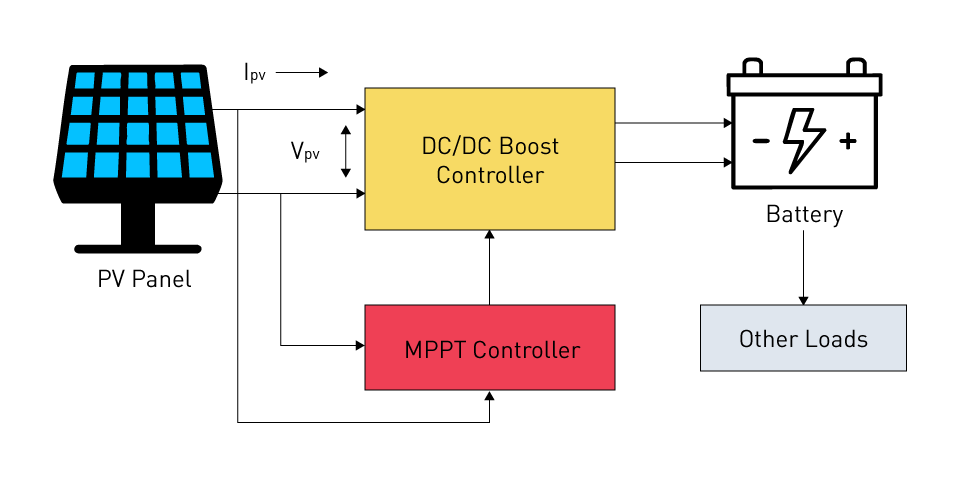
Figure 20: MPPT control
Inverter Control:
Function: Transforms DC energy from renewable sources into grid-compatible AC power.
Components:
- Pulse Width Modulation (PWM) Controllers: Supply the inverter with high-frequency switching signals.
- Voltage and Current Feedback Loops: Guarantee a stable and efficient conversion.
Grid Integration:
Function: Synchronizes the renewable energy system's output with the grid's voltage, frequency, and phase.
Components:
- Phase-Locked Loops (PLLs): Lock onto the phase and frequency of the grid.
- Analog Filters: Remove harmonics to provide a clean power output.
Design Example: Wind Turbine Inverter Control
System Requirements:
Energy Source: Wind turbine
Output Voltage: 230V AC (grid-compatible)
Power Rating: 1kW
Grid Synchronization: Maintain the frequency and phase aligned with the grid.
Components:
Wind Turbine: Generates electricity from wind energy.
AC/DC Converter: Converts the turbine's fluctuating AC output into DC.
DC/AC Inverter: Converts DC into grid-compatible AC.
PLL: Synchronizes the inverter's output with the frequency and phase of the grid.
Analog Filters: Remove high-frequency components by smoothing the inverter output.
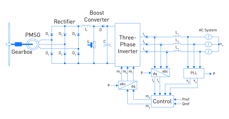
Figure 21: Wind generation system
Design Steps:
Step 1: AC/DC Conversion: Use a rectifier to convert the wind turbine's fluctuating AC output to DC.
Step 2: Inverter Control: Design the inverter with a PWM controller to provide a sinusoidal AC output.
Step 3: Grid Synchronization: To synchronize the inverter output with the grid, use a PLL.
Step 4: Filtering: To guarantee a clean sine wave output and eliminate high-frequency harmonics, use analog filters.
Testing and Optimization:
Prototype: Assemble the circuit together and connect it to the grid and wind turbine.
Synchronization Testing: Make that the grid and the inverter output are properly synchronized.
Efficiency Testing: To reduce losses, measure the system's efficiency and adjust the control parameters.
直接登录
创建新帐号