Types of Power Converters
In electrical and electronic systems, power converters are crucial components that allow electrical energy to be transformed from one form to another. The precise voltage, current, and frequency requirements of various applications must be met by this transformation. Designing and implementing effective power electronic systems requires an understanding of the many types of power converters and how they work.
AC/DC Converters (Rectifiers)
Rectifiers, also referred to as AC/DC converters, are devices that change alternating current (AC) into direct current (DC). Devices that run on DC voltage require this conversion in order to be powered.
Half-Wave Rectifier: only converts one-half of the AC waveform to DC using a single diode.
Full-Wave Rectifier: converts both half of the AC waveform to DC using a bridge rectifier configuration with four diodes or a center-tapped transformer with two diodes.
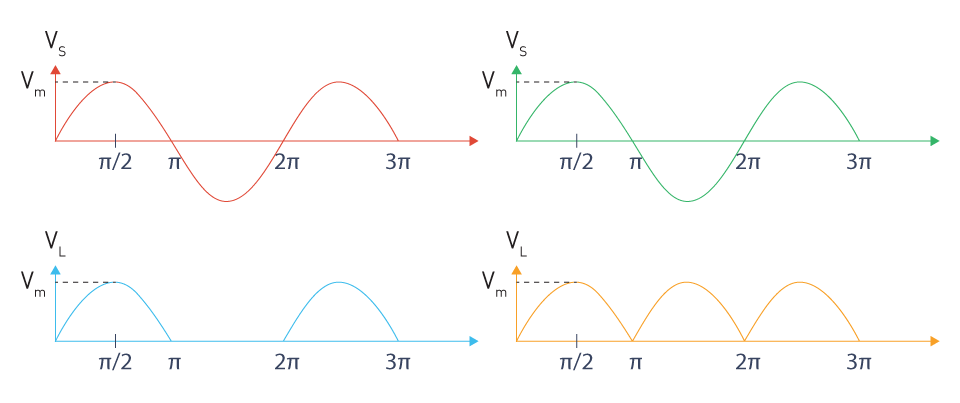
Figure 9: Half-wave vs. full-wave rectification
DC/DC Converters
DC/DC converters modify a DC power source's voltage level to satisfy the needs of particular loads. They have the ability to either step down (buck) or step up (boost) the voltage.
Buck Converter: Raises the output current while stepping down the input DC voltage to a lower output voltage.
Boost Converter: Lowers the output current while increasing the input DC voltage to a higher output voltage.
Buck-Boost Converter: Allows for flexible voltage conversion by having the ability to step up or step down the input voltage.
Cuk Converter: Offers an output voltage that is inverted and can be either higher or lower than the input voltage.

DC/AC Converters (Inverters)
Direct current (DC) is changed into alternating current (AC) using DC/AC converters, sometimes referred to as inverters. Applications like renewable energy systems and uninterruptible power supply, which need AC power from a DC source, require this.
Square Wave Inverter: Generates an output in the shape of a square wave that resembles an AC waveform.
Modified Sine Wave Inverter: Generates a stepped waveform that resembles a sine wave more than a square wave.
Pure Sine Wave Inverter: Generates a pure sine wave output that is nearly identical to grid power quality.
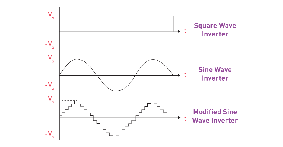
Figure 10: Inverter output waveform types
AC/AC Converters
Without first converting an AC power supply to DC, AC/AC converters alter its properties. These converters are used to change the AC power's voltage, frequency, or phase.
AC Voltage Controllers: Adjust the thyristors' firing angle to control the output voltage.
Cycloconverters: Use a matrix of controlled switches to directly convert AC power at one frequency to AC power at another frequency.
Matrix Converters: To achieve great efficiency and a small design, provide direct AC/AC conversion without an intermediate DC link utilizing bidirectional switches.
Basic Power Converter Circuit Topologies
Effective power conversion system design and execution rely heavily on power converter circuit topologies. The performance, efficiency, and complexity of the converter are influenced by these topologies, which dictate how power is processed and transformed. To choose and create suitable solutions for particular applications, engineers must have a thorough understanding of the various power converter topologies.
AC/DC Converter Topologies
Alternating current (AC) is converted to direct current (DC) using rectifiers, also known as AC/DC converters. To accomplish this conversion, a variety of topologies are available, each with unique benefits and uses.
Half-Wave Rectifier:
Topology: The load connected in series with a single diode.
Operation: Conducts during the AC input's positive half-cycle, preventing the negative half-cycle.
Advantages: Easy and inexpensive.
Disadvantages: High output ripple and low efficiency.
Applications: Simple, low-power uses where efficiency and ripple are not important considerations.
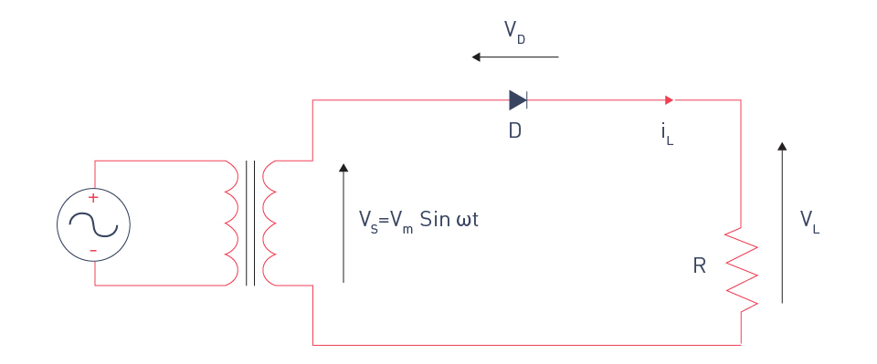
Figure 11: Single-phase half-wave diode rectifier
Full-Wave Rectifier:
Topology: Use a bridge configuration with four diodes or a center-tapped transformer with two diodes.
Operation: Converts the AC input's positive and negative half-cycles to DC.
Advantages: Reduced ripple and increased efficiency in comparison to half-wave rectifiers.
Disadvantages: Costlier and more complicated than half-wave rectifiers.
Applications: Extensively utilized in electronic device power supplies.
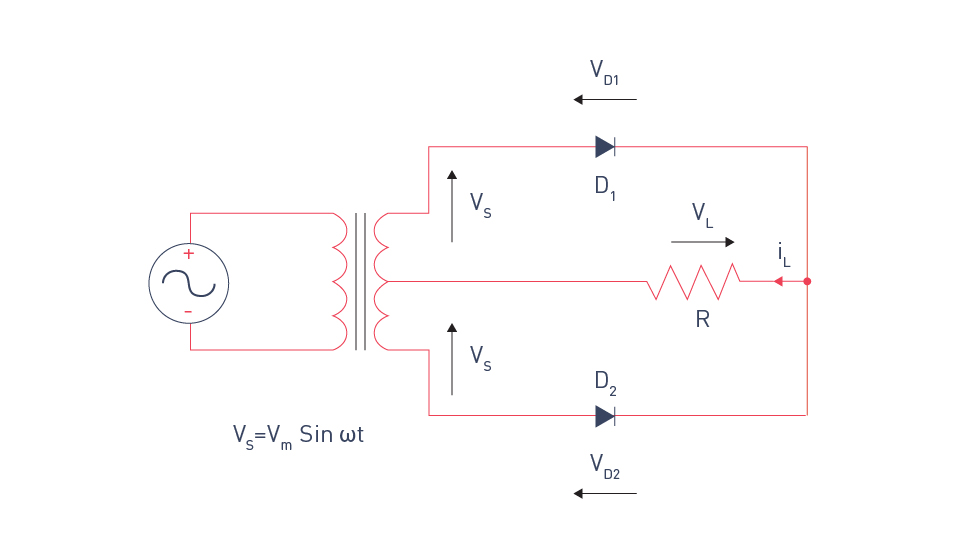
Figure 12: Full-wave rectifier with center-tapped transformer
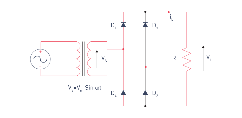
Figure 13: Bridge rectifier
DC/DC Converter Topologies
DC/DC converters modify a DC power source's voltage level to meet a particular load's requirements. Typical topologies include of:
Buck Converter:
Topology: Consists of a capacitor, diode, inductor, and switch (usually a transistor).
Operation: Reduces the output voltage by stepping down the input voltage.
Advantages: Simple design, high efficiency.
Disadvantages: Only reduces the voltage.
Applications: Battery chargers and microprocessor power supplies.
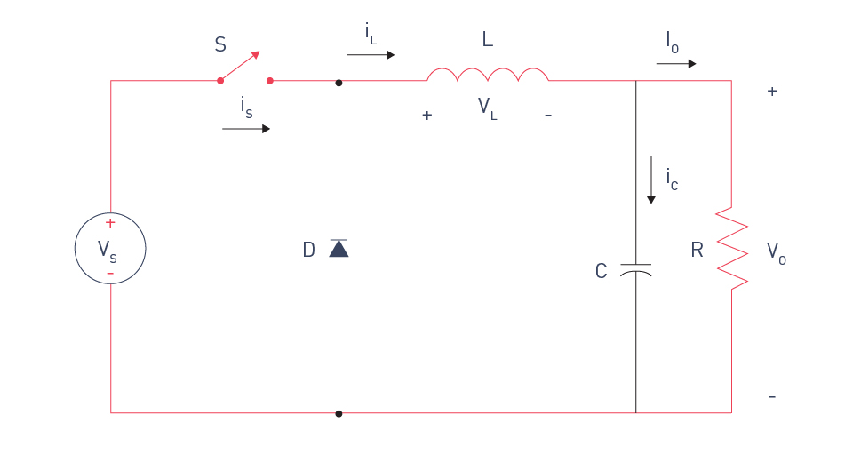
Figure 14: Buck converter
Boost Converter:
Topology: Consists of a capacitor, an inductor, a diode, and a switch.
Operation: Increases the output voltage by stepping up the input voltage.
Advantages: Simple design, high efficiency.
Disadvantages: Only increases the voltage.
Applications: Applications like portable devices require a higher voltage from a lower voltage source.
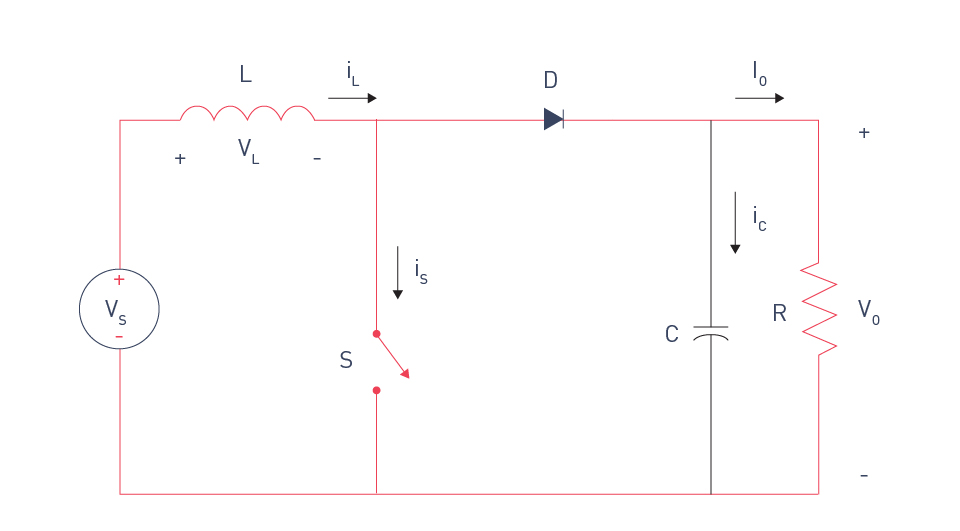
Figure 15: Boost converter
Buck-Boost Converter:
Topology: Blends features of boost and buck converters.
Operation: The input voltage can be stepped up or down.
Advantages: Versatile voltage conversion.
Disadvantages: Control is more complex.
Applications: Devices that run on batteries and require a steady output regardless of changes in the input voltage.
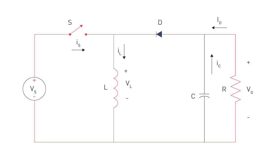
Figure 16: Buck-boost converter
Cuk Converter:
Topology: Incorporates inductors on both the input and output sides and uses a capacitor for transferring energy.
Operation: Provides an output voltage with reversed polarity that is either higher or lower than the input voltage.
Advantages: Effective energy transfer with low input and output ripple current.
Disadvantages: A more sophisticated design.
Applications: Applications that need voltage control and polarity inversion.
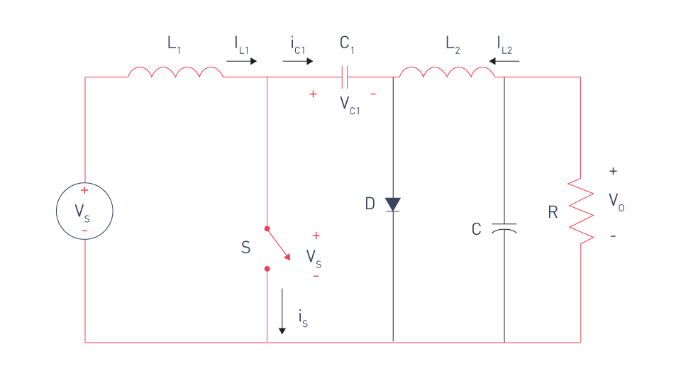
Figure 17: Cuk converter
DC/AC Converter Topologies
Direct current (DC) is converted to alternating current (AC) using DC/AC converters, also known as inverters. Common inverter topologies consist of:
Square Wave Inverter:
Topology: Simple circuit for switching.
Operation: Produces a wave output that is square.
Advantages: Easy and affordable.
Disadvantages: Harmonic distortion is significant and power quality is poor.
Applications: Simple applications where the quality of the waveform is not important.
Modified Sine Wave Inverter:
Topology: Stepped approximations are used to represent a sine wave.
Operation: It generates a waveform that is closer to a sine wave than a square wave.
Advantages: Power quality is superior to square wave and more cost effective.
Disadvantages: Still has harmonic distortion.
Applications: General-purpose use in residential and small-business settings.
Pure Sine Wave Inverter:
Topology: Uses filter circuits and pulse width modulation (PWM).
Operation: Generates a clean sine wave output.
Advantages: Excellent power quality, suitable for sensitive electronics.
Disadvantages: More costly and complex.
Applications: High-end devices like audio/visual systems and medical equipment that demand premium power.
AC/AC Converter Topologies
Without first converting an AC power source to DC, AC/AC converters alter its properties. These converters can change the phase, frequency, or voltage.
AC Voltage Controllers:
Topology: Operates by connecting thyristors or triacs in series with the load.
Operation: Adjusts the switches' firing angle to regulate the output voltage.
Advantages: Easy and efficient way to regulate voltage.
Disadvantages: Adds harmonics, limited to voltage control.
Applications: AC motor speed control, heater control, and light dimming.
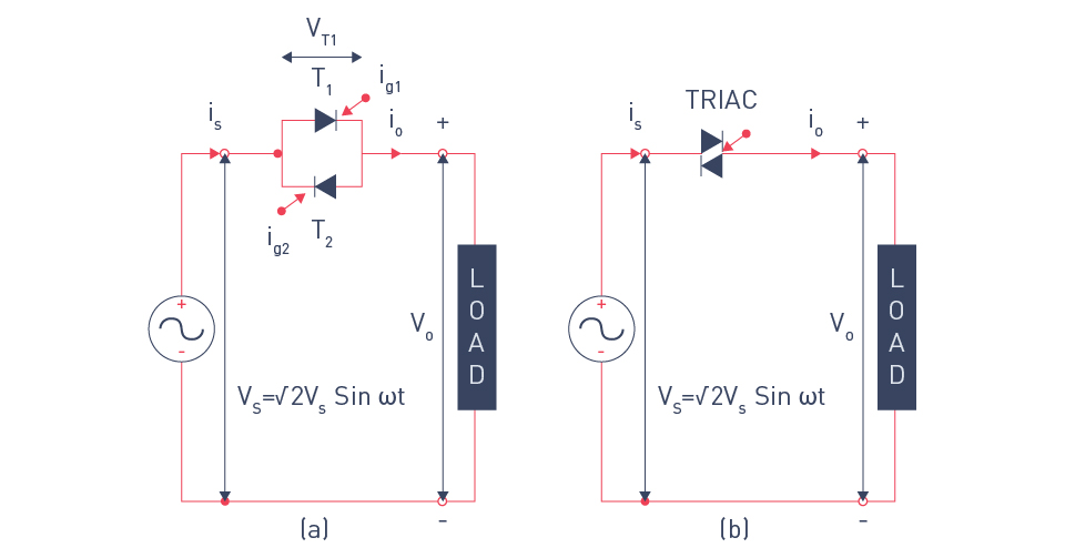
Figure 18: Single-phase full-wave voltage controller (a) with SCRs (b) with TRIAC
Cycloconverters:
Topology: uses several thyristors set up in a matrix.
Operation: AC electricity at one frequency can be directly converted to AC power at another frequency.
Advantages: Accurate frequency regulation, appropriate for large motors.
Disadvantages: Costly, complicated, and has a narrow frequency range.
Applications: Variable speed drives for rolling mills and huge motors.
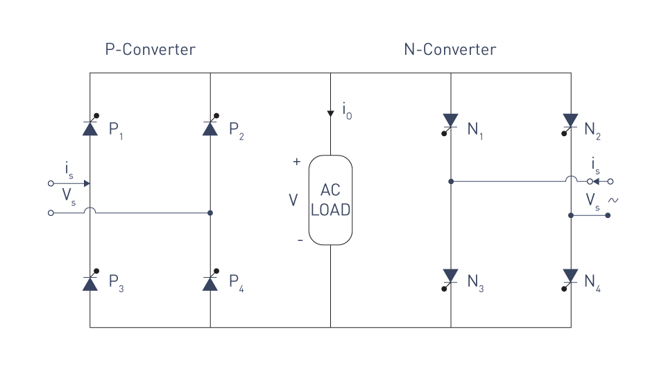
Figure 19: Single-phase bridge cycloconverter
Matrix Converters:
Topology: Consists of a matrix of bidirectional switches.
Operation: Eliminates the need for a middle DC link by offering direct AC/AC conversion.
Advantages: Small, effective, and able to provide high-quality power.
Disadvantages: Control algorithms are complex.
Applications: Advanced motor drives for applications that require great efficiency and small design.
Operating Modes
Operating modes in power conversion circuits relate to the various ways in which these circuits can operate to accomplish efficient power conversion. Understanding these modes is critical for maximizing performance, efficiency, and reliability in a variety of applications. Each mode has unique characteristics and is chosen based on the individual needs of the power conversion task.
Continuous Conduction Mode (CCM)
Continuous Conduction Mode occurs when the current through a power converter's inductor or transformer never reaches zero throughout the switching cycle. This mode is distinguished by a constant flow of current, resulting in reasonably smooth functioning.
Characteristics:
- The current through an inductor never reaches zero.
- Reduced ripple in current when compared to DCM (discontinuous conduction mode).
- Usually results in less switching losses and increased efficiency.
Applications:
- Appropriate for high-power applications where it's crucial to keep the current constant.
- Frequently found in computer power supplies, telecommunication equipment, and other systems with high demand.
Discontinuous Conduction Mode (DCM)
When the current flowing through the transformer or inductor drops to zero during a part of the switching cycle, this is known as discontinuous conduction mode. Higher current ripple results from the pulsing current that characterizes this mode.
Characteristics:
- With every switching cycle, the inductor current decreases to zero.
- Greater peak currents than those of CCM.
- Usually leads to increased switching losses, although control tactics can be made simpler.
Applications:
- Ideal for low- to medium-power applications where cost-effectiveness and ease of use are more important than efficiency.
- Frequently used in small power supplies, low-power adapters, and battery chargers.
Critical Conduction Mode (CRM)
When the converter runs precisely at the CCM/DCM boundary, it enters Critical Conduction Mode, also referred to as Boundary Conduction Mode. At the precise end of every switching cycle, the inductor current drops to zero.
Characteristics:
- Combines the benefits of both CCM and DCM.
- High efficiency can be attained with comparatively easy control.
- Adjusts to maintain critical conduction by operating at variable frequency.
Applications:
- Ideal for several kinds of DC/DC converters and power factor correction (PFC) circuits.
- Frequently used in medium-power applications, PFC pre-regulators, and LED drivers.
Fixed Frequency Mode
Regardless of the load or input voltage conditions, the power converter operates at a fixed switching frequency when in fixed frequency mode. Although this mode makes design and management easier, it could necessitate more complex filtering to control EMI and noise.
Characteristics:
- The switching frequency remains constant.
- Simplifies control loop and filter design.
- Complex filtering may be necessary to control electromagnetic interference (EMI) and noise.
Applications:
- Ideal for devices like precision power supplies and communication equipment where a stable switching frequency is essential.
- Frequently utilized in RF circuits, audio amplifiers, and regulated power supplies.
Variable Frequency Mode
The switching frequency in variable frequency mode varies according to changes in input conditions or load. Although this mode makes control and filtering challenging, it can increase efficiency and lower switching losses.
Characteristics:
- Depending on the input and load conditions, the switching frequency changes.
- Can decrease switching losses at small loads while increasing efficiency.
- Calls for more complex filtering and control strategies.
Applications:
- Ideal for energy-saving devices and dynamic power systems, among other applications where efficiency at varying loads is crucial.
- Frequently utilized in adaptive power supplies, renewable energy converters, and variable frequency drives (VFDs).
Burst Mode
Burst Mode, sometimes referred to as Pulse Skipping Mode, controls the output voltage by periodically turning the converter on and off. For light loads, this mode is especially helpful in lowering power usage.
Characteristics:
- The converter reduces switching activity at light loads by operating in bursts.
- Greatly lowers power usage when in low-power or idle conditions.
- Can add more ripple and noise to the output.
Applications:
- Ideal for standby power supplies and battery-powered devices where low power consumption is crucial.
- Frequently utilized in energy-efficient power supplies, laptops, and mobile phones.
Introduction to Control Techniques
To maximize efficiency, maintain system stability, and regulate output voltage and current, power converters employ control techniques. Pulse width modulation (PWM), a basic power electronics technique that modifies the duty cycle of a periodic signal to regulate the power given to a load, is one example of a common control technique. PWM's efficiency, ease of usage, and effectiveness in regulating a converter's output voltage, current, or power make it popular. To accomplish accurate and effective power conversion, a number of additional control strategies are used in addition to PWM.
Pulse Width Modulation (PWM)
In PWM, a power transistor is switched at a high frequency between the on and off states. The average value of the output voltage or current is determined by the duty cycle, which is the ratio of the signal's on-time to the total period. Depending on the application and controller type, pulse width modulation (PWM) control can be applied to both analog and digital systems.
Principle of Operation:
Duty Cycle: The duty cycle ((D) is defined as T_on/T, where Ton is the time the switch is active and T is the total duration of the switching cycle. Adjusting D controls the average output voltage (Vout).

Figure 20: PWM duty cycles
Average Output Voltage: Vout = D ∙ Vin for a buck converter, where Vin is the input voltage. The output voltage can be changed to the appropriate level by adjusting D.
Advantages of PWM:
High Efficiency: PWM is very effective since it minimizes the switch's power loss when it is fully on or off.
Precise Control: Through duty cycle adjustment, PWM enables exact control of the output voltage or current.
Simplicity: PWM is a cost-effective solution for many applications because of its very simple basic implementation.
Applications of PWM:
DC/DC Converters: PWM regulates the output voltage in buck, boost, and buck-boost converters.
Motor Control: PWM modifies the average voltage provided to DC motors to regulate its speed and torque.
Inverters: PWM converts DC sources into AC waveforms, allowing the use of renewable energy and uninterruptible power supplies (UPS).
Other Control Techniques
While PWM is commonly utilized, additional control techniques are used in power conversion to fulfill specific needs and increase performance.
Hysteresis Control:
Principle: Hysteresis control, sometimes referred to as bang-bang control, controls the output by turning the converter on and off in response to the output voltage deviating from a reference value.
Advantages: Easy to use and quick transient response.
Applications: Ideal for devices like battery chargers and basic DC/DC converters that need fast response and moderate accuracy.
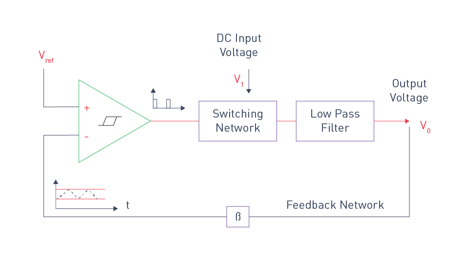
Figure 21: DC/DC converter with hysteresis control
Voltage Mode Control (VMC):
Principle: In voltage mode control, a compensator processes the error signal after comparing the output voltage to a reference voltage in order to modify the PWM duty cycle.
Advantages: Excellent performance and stability at a fixed frequency.
Applications: Frequently used in converters and power supplies that need accurate voltage regulation.
Current Mode Control (CMC):
Principle: Current mode control measures the inductor current and compares it to a reference current. The ensuing error signal changes the PWM duty cycle.
Advantages: Inherent overcurrent protection and improved transient response.
Applications: Extensively utilized in power factor correction (PFC) circuits, motor controllers, and DC/DC converters.
Digital Control:
Principle: Digital control offers flexibility and accuracy by implementing control algorithms in software using microcontrollers or digital signal processors (DSPs).
Advantages: Extremely programmable, enabling adaptive control and complex control strategies.
Applications: utilized in smart grid applications, renewable energy systems, and advanced power supplies.
Sliding Mode Control (SMC):
Principle: A variable structure control method called "sliding mode control" compels the system state to "slide" toward the intended equilibrium point along a predefined surface.
Advantages: Robustness to external disruptions and parameter alterations.
Applications: Ideal for high-precision power systems and aerospace applications that demand excellent performance and robustness.
直接登录
创建新帐号