Fundamental Safety Standards for Power Electronic Devices
Power electronic devices, which are used in a wide range of applications from industrial automation to consumer electronics, must meet fundamental safety standards to safeguard users and equipment from hazards such as electromagnetic interference, electric shock, and overheating. These safety standards, which include IEC 60950 for IT equipment, UL 508 for industrial control equipment, and IEC 62368 for audio/video, IT, and communication technology equipment, set forth essential requirements that manufacturers must fulfill to guarantee the safety of their devices.
Control strategies that actively monitor and regulate the device's operational parameters are essential to meeting these standards. By identifying anomalous conditions, initiating preventative measures, and guaranteeing safe operation in all conditions, effective control strategies help mitigate risks. Key control strategies that help power electronics adhere to safety standards are listed below.
Overvoltage and Overcurrent Protection
Overvoltage and overcurrent are serious safety issues in power electronics because they can result in component failure, fire, or electric shock. Control systems must constantly monitor the device's voltage and current levels and respond swiftly to avoid dangerous spikes or surges.
Table 4: Overvoltage vs. overcurrent
| Aspect | Overvoltage | Overcurrent |
|---|---|---|
| Definition | Occurs when the voltage exceeds the rated value of a system | Occurs when the current exceeds the rated value of a system |
| Example | High voltage from a power surge damaging electronics | Overheating of wires or appliances due to excess current |
| Cause | Voltage spikes, lightning strikes, power surges, or faults in the supply network | Short circuits, equipment malfunctions, or overload conditions |
| Effects | Can damage electrical components, insulation, and circuits | Can overheat wiring, damage equipment, or cause fires |
| Protection | Voltage surge protectors, voltage suppressors, fuses, and circuit breakers | Circuit breakers, fuses, and current limiting devices |
Overvoltage Protection (OVP): OVP strategies include identifying when the voltage exceeds a safe threshold and responding to reduce the excess. This can involve shutting off the system or rerouting the excess energy through clamping circuits such as transient voltage suppression (TVS) diodes or metal-oxide varistors (MOVs).
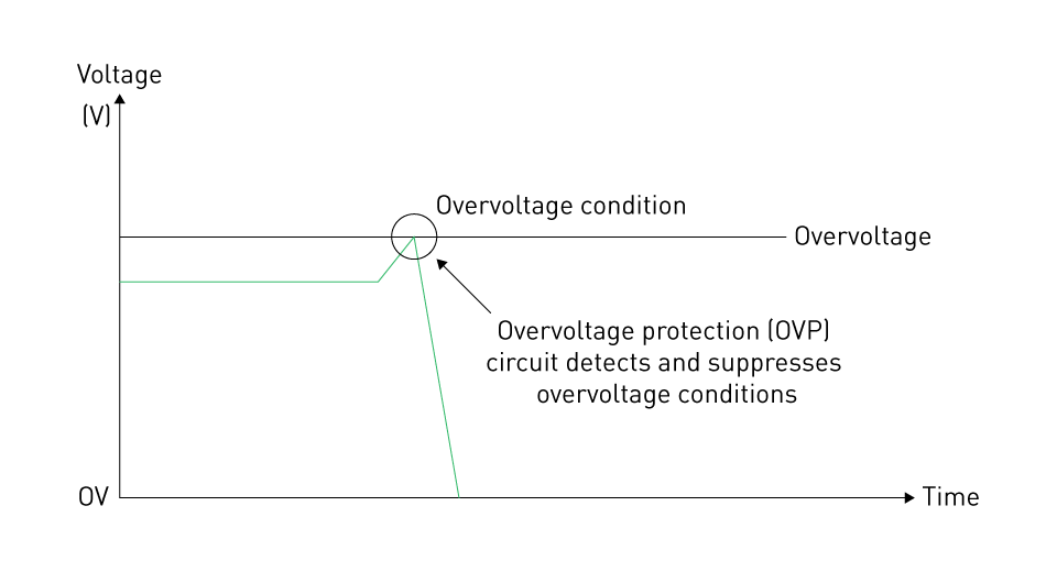
Figure 2: Overvoltage protection
Overcurrent Protection (OCP): To identify abnormal current flow, OCP strategies rely on current sensors. Control systems can initiate preventive actions such as load shedding, current limiting, or circuit breaker in the event of an overcurrent condition.
Power electronics can adhere to safety standards that demand strong protection against overvoltage and overcurrent conditions, such as IEC 61010 (safety requirements for electrical equipment for measurement, control, and laboratory use), by implementing these control strategies.
Thermal Management and Overheating Protection
In power electronics, thermal management is essential because high temperatures can degrade components, decrease efficiency, and compromise safety. To prevent fires and guarantee long-term reliability, safety standards such as IEC 60601 (for medical electrical equipment) emphasize the importance of temperature control.
Temperature sensors are used by control systems to monitor the internal temperature of essential components including capacitors, diodes, and power transistors. Several control strategies can be used when the system determines that the temperature is getting close to dangerous levels:
Dynamic Thermal Management (DTM): In response to increasing temperatures, DTM modifies the operating frequency or power output to minimize heat generation.
Active Cooling Systems: When passive cooling techniques (such as heat sinks) are not sufficient to dissipate excess heat, control systems might turn on fans, pumps, or other cooling mechanisms.
Overtemperature Shutdown: The control system can initiate a complete shutdown if the temperature rises above critical thresholds to prevent further damage or hazardous conditions.
These thermal management techniques are crucial for guaranteeing compliance with safety standards such as IEC 60950, which mandates that devices include safeguards against overheating.


Ground Fault Protection and Insulation Monitoring
Ground faults pose serious safety risks in power electronics because they happen when a live conductor comes into touch with grounded surfaces. To avoid electric shock or equipment damage, control systems are in charge of identifying ground faults and initiating corrective actions. Ground fault protection requirements are outlined in standards such as IEC 61558 (safety of power transformers) and IEC 60364 (low-voltage electrical installations).
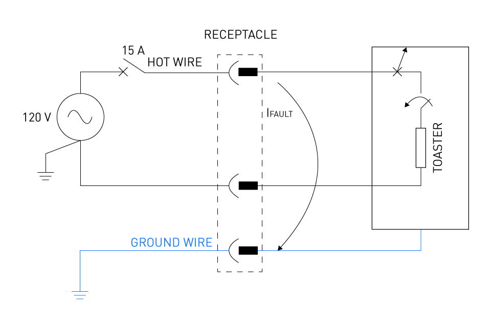
Figure 3: Ground fault
Ground fault protection control strategies include the following:
Ground Fault Circuit Interrupters (GFCIs): To identify small differences in current between the live and neutral conductors, GFCIs are integrated into control systems. The control system instantly disconnects the circuit's power if it detects a ground fault.
Insulation Monitoring Devices (IMDs): In ungrounded systems, IMDs are utilized to continuously monitor the live conductors' insulation resistance. To avoid hazardous scenarios, the control system alerts the operator or shuts down the system if the insulation deteriorates and a ground fault is imminent.
Monitoring strategies for insulation and ground fault aid in ensuring compliance with safety standards that address the risk of electric shock, such as IEC 60204 (safety of machinery).
Fault Detection and Diagnostic Systems
Advanced control systems provide diagnostic, and fault detection features that monitor the device for unusual activity or deteriorating performance over time. Early fault detection and failure prevention are essential, according to safety standards such as IEC 61508 (functional safety of electrical, electronic, and programmable systems).
Key control strategies for fault detection include the following:
Self-Diagnostics: Self-diagnostic tests are continuously performed by control systems to verify the integrity of components such as actuators, sensors, and converters. Any fault detected results in safe shutdowns or trigger warnings.
Redundancy and Fail-Safe Mechanisms: Redundant sensors or control paths can be employed to keep the system operational even if one component fails. Fail-safe mechanisms, such as transfer to backup systems or automatic shutdown, keep the system safe during a fault.
Predictive Maintenance: Control systems can predict when components are likely to fail and alert operators to perform maintenance before a catastrophic failure happens by examining operational data and trends.
In addition to improving safety, these fault detection, and diagnostic strategies also increase power electronics' reliability and lifespan while guaranteeing compliance with strict safety standards.
Control of Isolation Barriers
Power electronic devices frequently operate at high voltages, and it is crucial to maintain electrical isolation between circuit sections to avoid hazardous voltage transfer. For example, IEC 62109 (safety of power converters for use in photovoltaic power systems) specifies isolation standards to ensure safety in high-voltage applications.
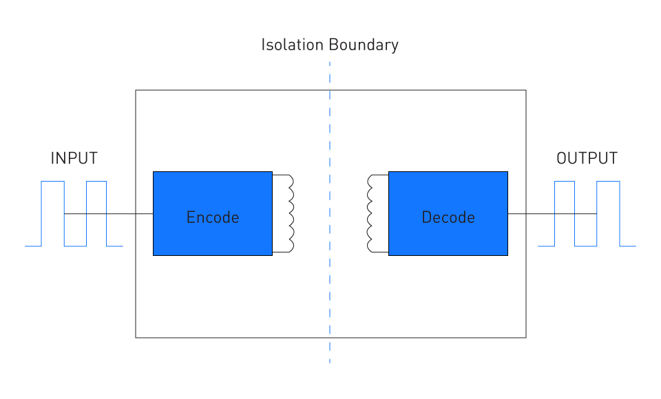
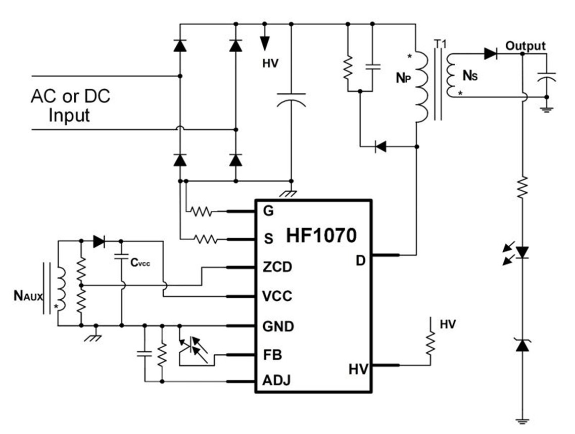
Figure 4: Example of galvanic (inductive) isolation between circuit sections
Control systems help manage isolation barriers by:
Monitoring Isolation Integrity: Transformers and optocouplers are examples of isolation components that control systems monitor to ensure they are operating properly and maintaining the necessary isolation levels.
Switching Isolation Devices: Control systems regulate isolation switches to stop voltage transfer across isolated circuit sections in systems with multiple power sources or outputs.
Control systems assist power electronics in meeting isolation-related safety standards by maintaining robust isolation and monitoring procedures, guaranteeing that operators and users are protected from high-voltage risks.
Risk Assessment and Safety Compliance Procedures
Risk assessment and compliance procedures are essential for ensuring the safety of power electronic devices. These procedures aid in locating any dangers, assessing the risks linked to the device's operation, and implementing measures to minimize those risks. International safety standards such as ISO 14971 (Risk Management for Medical Devices) and IEC 61508 (Functional Safety of Electrical, Electronic, and Programmable Electronic Safety-related Systems) require a structured approach to risk management in power electronics, where devices operate under high voltages and currents.
Risk Assessment Process
The power electronics risk assessment procedure involves a systematic analysis of the potential risks that can materialize during regular operation, malfunction, or breakdown of the device. This procedure usually consists of the following steps:
Hazard Identification: The first step in risk assessment is to identify all potential hazards associated with the devices. This covers mechanical risks (such as component failure), thermal risks (such as overheating), electrical risks (such as electric shock or short circuits), and environmental risks (such electromagnetic interference or moisture exposure).
Risk Estimation: After identifying the hazards, the next step is to calculate the risk that each hazard poses. This involves evaluating both the risk of the hazard materializing and the extent of its potential impacts.
$$ \text{Risk} = \text{Likelihood} \times \text{Impact} = P(E) \times C(E) $$P(E) is the probability of an event, while C(E) is its consequences.
A high-voltage short circuit, for example, can have serious consequences, whereas slight voltage variations might be less dangerous. Risk matrices, which classify risk levels according to likelihood and severity, are frequently used to quantify risk.
Risk Evaluation: The next step after risk estimation is to determine if the risk level is acceptable or if mitigation is necessary. Guidelines for acceptable risk levels, which differ based on the application and operating environment, are frequently provided by international safety standards. Critical systems, such as medical devices and automotive electronics, must meet higher safety standards than consumer electronics.
Risk Control: Control measures must be implemented to minimize or eliminate risks that are considered unacceptable. These precautions can involve redesigning components, installing control systems that continuously monitor and regulate operating parameters, or installing protection circuits. One way to reduce the possibility of excessive current harming the system or causing fire hazards is to install an overcurrent protection circuit.
Risk Acceptance: Once control measures are implemented, the risks are reviewed to determine whether the residual risk (the risk that remains after control measures are applied) is acceptable. More control measures might be required if the residual risk is still too high.
Safety Compliance Procedures
Following the risk assessment process, formalized procedures must be implemented to assure compliance with safety standards. To guarantee that power electronic devices fulfill safety, quality, and performance standards prior to being released onto the market, regulatory bodies and organizations such as IEC, UL, and ISO have established safety compliance procedures.
Design Verification and Validation: Compliance starts with the design stage, when the safety features discovered during the risk assessment process are integrated into the device. While design validation verifies that the device operates safely in real-world operating conditions, design verification ensures that the safety features operate as intended. Thermal stress testing, circuit simulation, and hardware-in-the-loop (HIL) testing are some methods of verification. Testing the product in its intended environment to ensure it satisfies all operational safety requirements is part of validation.
Safety Testing and Certification: To meet international standards, power electronic devices must undergo thorough safety testing in certified laboratories. Common tests include:
- Dielectric Strength Testing: To guarantee that there is sufficient insulation between electrical components to prevent an electrical breakdown.
- Temperature Testing: To ensure that the device functions within acceptable temperature limits, hence preventing overheating and fire hazards.
- Electromagnetic Compatibility (EMC) Testing: To ensure that the device can withstand external interference and emits minimal electromagnetic interference (EMI).
Certifications such as UL (Underwriters Laboratories) or CE (ConformitéEuropéenne) marking, which indicate compliance with international safety standards, are given to devices that complete these tests. Devices that have been certified can then be used and sold in specific regions or industries.
Documentation and Traceability: In the compliance process, proper documentation is essential. All safety testing, risk analyses, and design modifications must be meticulously documented by manufacturers. These records are necessary to get safety certifications and serve as proof of compliance. In the event of a product recall or failure, detailed documentation aids in determining the cause and identifying corrective actions.
Post-Market Surveillance and Compliance Maintenance: Certification of a product is not the end of compliance. To ensure long-term safety, manufacturers must monitor devices after they are issued to the market. This procedure, called post-market surveillance, involves gathering and examining data from safety incidents, customer reviews, and field performance. If new risks are identified, manufacturers must take corrective actions and upgrade safety features to mitigate them. Throughout the product's lifecycle, this continual monitoring is crucial to guaranteeing consistent adherence to safety standards.
Safety Control Strategies
Control strategies that continuously monitor and regulate device operation are essential to ensuring safety compliance. These strategies include the following:
Real-Time Monitoring: Sensors and control systems allow devices to identify abnormalities such as insulation degradation, overvoltage, and overheating. To avoid dangerous situations, real-time monitoring systems initiate corrective measures such as lowering power or turning off the device.
Self-Diagnostics: Self-diagnostic systems that conduct routine checks to guarantee the integrity of safety features are incorporated into many power electronic devices. The device can give alerts or initiate safety shutdowns if a fault is detected.
Safety-Critical Software: Software must adhere to international safety standards such as IEC 61508 (Functional Safety) in systems that rely on microcontrollers or programmable logic controllers (PLCs) for safety functions. To ensure it responds to potential risks reliably, safety-critical software is rigorously tested.
Key International Standards for Risk Assessment and Safety Compliance
Risk assessment and safety compliance for power electronic devices are governed by several international standards. Among the most well-known are the following:
IEC 61508: In addition to providing guidance for safety integrity levels (SILs), risk assessment, and hazard identification, this standard outline general requirements for functional safety in electrical and electronic systems.
ISO 14971: This standard provides a framework for risk management, covering risk analysis, risk evaluation, and risk control, and is mostly utilized in the medical device industry.
UL 508: UL 508 deals with standards for ensuring safety, performance, and reliability in high-power applications with a focus on industrial control equipment.
IEC 62368: With a focus on hazard-based risk assessment, this standard covers the safety requirements for communication, audio-visual, and information technology equipment.
Design Considerations for Meeting Safety Standards
It takes more than just following the regulations to design power electronic devices to fulfill safety standards; careful consideration of component selection, circuit design, thermal management, and control strategies are all necessary. These considerations contribute to the safe and reliable operation of devices in both normal and fault conditions. A comprehensive design strategy that incorporates safety at every stage of development is necessary to comply with international safety standards, such as UL 508 for industrial control systems, IEC 60950 for IT equipment, and IEC 61508 for functional safety. Key design considerations that aid in meeting these safety standards are listed below.
Component Selection and Ratings
The selection of components, including resistors, diodes, transistors, and capacitors, is essential in guaranteeing the reliability and safety of power electronic systems. Components must be rated to exceed the required safety margins and withstand the worst-case operational conditions.
Voltage and Current Ratings: To avoid breakdowns, overheating, and the risk of electric shock, components must be rated higher than the maximum operating voltage and current. For example, due to their high breakdown voltages, insulated-gate bipolar transistors (IGBTs) and power MOSFETs are frequently used in high-voltage systems.
Temperature Ratings: Components must be rated to withstand thermal stress and temperature fluctuations. This is especially crucial for capacitors and semiconductors, as they can deteriorate at high temperatures, jeopardizing both performance and safety. As required by IEC 60601 and IEC 61508, designers must ensure that all components operate within their specified thermal limits.
Insulation and Creepage Distances: In power electronics, insulation is an essential safety feature that guards against electric shocks and short circuits. Guidelines for clearance (the shortest distance through air) and creepage (the shortest distance along a surface between two conductive parts) are provided by standards such as IEC 60950 and IEC 62368, which ensure sufficient insulation is maintained to prevent dielectric breakdown under high-voltage conditions.
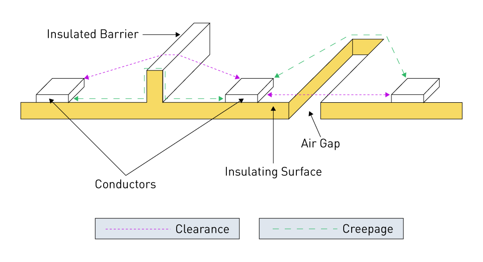
Figure 5: Creepage and clearance
Thermal Management
For power electronics to meet safety standards, effective thermal management is essential. It is essential to design systems that dissipate heat efficiently since excessive heat can cause component failure, decreased performance, and even fire hazards.
Heat Sinks and Thermal Pads: Common techniques for enhancing heat dissipation in power components such as MOSFETs, diodes, and IGBTs include the use of heat sinks and thermal pads. As mandated by IEC 60950 and IEC 61508, designers must calculate these components' thermal resistance and select heat sinks that can maintain component temperatures within safe limits.
Forced Air or Liquid Cooling: Passive cooling, such as heat sinks, may not be sufficient in high-power applications. To maintain temperature levels within safety limits, forced air cooling, fans, or liquid cooling systems may be necessary. The requirements for efficient cooling and heat management in residential and industrial systems are outlined in UL 508 and IEC 60335.
Thermal Shutdown Protection: Thermal sensors can be incorporated into the design to further improve safety by detecting overheating and starting shutdown procedures to stop component damage or fire. To avoid dangerous temperature conditions, standards such as IEC 62368 require thermal shutdown protection in critical systems.
Isolation and Grounding
To ensure user safety and compliance with standards such as IEC 60601 and IEC 60950, electrical isolation and grounding are crucial design features. Equipment and users are shielded from high-voltage risks and electric shock by proper isolation and grounding.
Table 5: Isolation vs. grounding
| Feature | Isolation | Grounding |
|---|---|---|
| Purpose | Prevents unwanted current flow between circuits | Provides a path for fault currents to return to the earth |
| Function | Breaks electrical connection to eliminate noise | Establishes a reference point for voltage stability |
| Effect | Reduces interference, protects equipment | Prevents electric shock, stabilizes voltage |
| Safety Role | Protects sensitive equipment from surges | Ensures equipment and human safety by preventing electrical hazards |
Transformer and Optocoupler Isolation: Power converters employ optical (optocouplers) or inductive (transformers) isolation. For example, flyback converters shield users from excessive voltages by isolating the input from the output using transformers. In feedback circuits, optocouplers are frequently employed to provide electrical isolation between the power and control stages.
Proper Grounding: For safety and electromagnetic compatibility (EMC), it is essential to ensure the system is grounded properly. By providing a safe path for fault currents and preventing the accumulation of static charge, grounding lowers the chance of electric shock. The best practices for grounding electrical systems to guarantee user safety are outlined in standards such as IEC 60364 and IEC 61558.
Overcurrent and Overvoltage Protection
Power electronic systems can fail catastrophically due to overcurrent and overvoltage, which can result in component damage, fires, and safety risks. Systems must be designed with proper protection mechanisms to meet safety standards such as UL 508 and IEC 61010 (for measurement, control, and laboratory use).
Fuse and Circuit Breaker Protection: In the event of an overcurrent or short circuit, fuses and circuit breakers cut down the current flow, offering primary protection. For the worst-case current surge to be handled without nuisance tripping, designers must select fuses and breakers with appropriate ratings.
Table 6: Fuses vs. circuit breakers
| Feature | Fuses | Circuit Breakers |
|---|---|---|
| Function | Protects against overcurrent by melting a wire | Automatically interrupts current flow when excessive current is detected |
| Resetability | Single-use; must be replaced after blowing | Can be reset after tripping |
| Response Time | Fast, typically reacts in milliseconds | Slower than fuses but still fast enough for protection |
| Cost | Generally cheaper | Typically more expensive |
Transient Voltage Suppression (TVS) Diodes and MOVs: Metal oxide varistors (MOVs) and TVS diodes are crucial components for shielding systems from voltage transients such as switching surges or lightning strikes. By safely clamping high voltages, these devices preserve IEC 61000-4-5 (surge immunity standards) compliance and protect against damage to sensitive electronic components.
Table 7: TVS diodes vs. MOVs
| Feature | TVS Diodes | MOVs |
|---|---|---|
| Function | Protects circuits from voltage spikes and transients | Absorbs and dissipates high voltage surges |
| Response Time | Extremely fast, in picoseconds to nanoseconds | Slower than TVS diodes, but still fastenough for protection |
| Clamping Voltage | Lower clamping voltage, more precise protection | Higher clamping voltage, less precise |
| Durability | Typically better for repetitive transients | Can degrade with repeated surges |
Crowbar Circuits and Zener Diodes: Crowbar circuits, which are commonly implemented with silicon-controlled rectifiers (SCRs), and Zener diodes can be used to redirect excess voltage and prevent overvoltage conditions. By preventing sensitive components from being exposed to hazardous voltage levels, these methods ensure compliance with safety standards.
Fault Detection and Safety Redundancy
Power electronic systems must be designed with redundancy mechanisms and fault detection to stop failures from causing hazardous conditions and to meet the strict reliability and safety requirements specified in standards such as IEC 61508.
Real-Time Fault Monitoring: Overcurrent, overvoltage, and overheating are examples of abnormal operating conditions that integrated fault monitoring circuits can identify and respond to. These systems ensure that faults are detected in real time and initiate preventative measures such as turning off the system or activating redundant systems.
Redundant Safety Circuits: Redundant safety circuits may be necessary in important applications, such as industrial controls or medical devices, to guarantee continuous safe operation even if a system component fails. To preserve system integrity in the event of a failure, redundant power supplies, sensors, or controllers, for example, can take over.
Electromagnetic Compatibility (EMC)
Electromagnetic interference (EMI) can pose serious safety hazards by interfering with the operation of sensitive components or nearby systems. Designers must ensure the system is resistant to external electromagnetic disturbances and does not emit excessive interference to satisfy the EMC requirements specified in IEC 61000 and CISPR standards.
Filtering and Shielding: In power electronic systems, EMI must be minimized through proper filtering and shielding. To suppress high-frequency noise and prevent it from radiating into the environment, components such as ferrite beads, common-mode chokes, and EMI filters can be used.
PCB Layout for EMC: The layout of a printed circuit board (PCB) is crucial for controlling electromagnetic emissions. EMC standards can be met by the system by minimizing EMI through careful component placement, grounding planes, and signal routing.
Design for Fail-Safe Operation
Power electronic systems in safety-critical applications must be designed to fail safely so that, in the case of a failure, the system doesn't present a risk. Principles of fail-safe design are especially essential when adhering to ISO 13849 (machinery safety) and IEC 61508 (functional safety).
Safe State in Case of Failure: In the event of a failure, the system needs to be designed to automatically transition to a safe state. For example, if an internal fault is identified, a power supply might shut down or switch to a limited output mode to avoid hazardous conditions.
Graceful Degradation: Systems may occasionally be designed to function at a reduced capacity instead of shutting down entirely. This method, called graceful degradation, guarantees that essential functions continue even when there are faults.
Case Studies: Real-World Examples of Safety Compliance in Power Electronics
To prevent hazards such as electric shock, fire, and system malfunctions, power electronics must adhere to safety standards. In addition to being required by law, adhering to the necessary safety standards is essential for safeguarding both users and equipment. The following case studies provide real-world examples of how different power electronic systems achieved safety compliance.
Case Study 1: Safety Compliance in Electric Vehicle (EV) Chargers
To ensure user safety and reliable operation, electric vehicle (EV) chargers must adhere to strict safety standards and operate at high power levels. Safety issues with EV chargers include electromagnetic compatibility (EMC), thermal management, and electric shock risks. To guarantee that chargers are safe for customers to use, standards such as IEC 60364-7-722 (requirements for electrical installations of EV charging stations) and IEC 61851 (electric vehicle conductive charging system) must be followed.
Safety Challenges:Ensuring the safety of both users and the vehicle is one of the primary challenges in the design of EV chargers. To prevent the risk of electric shock, EV chargers must manage high voltage and current levels. Thermal control is also essential to avoid overheating during long charging cycles. Additionally, chargers must adhere to IEC 61000 series standards to reduce electromagnetic interference.
Solution:To solve these challenges, manufacturers incorporate a variety of safety features, including:
- Isolation methods and insulation barriers to reduce the risk of electric shock.
- Protection circuits and thermal sensors for monitoring and regulating heat generation while charging.
- Residual current devices (RCDs) monitor leakage currents and instantly disconnect the power supply when unsafe amounts are detected.
- Proper grounding and EMC filters to meet immunity and emission requirements.
The EV chargers passed certification testing after implementing these strategies and adhering to the proper IEC safety standards, allowing them to be legally marketed and used globally.
Case Study 2: Safety Compliance in Power Supplies for Medical Devices
Since malfunctions can have a direct effect on patient safety, medical devices are subject to some of the strictest safety standards. IEC 60601-1, which establishes the overall requirements for basic safety and essential performance in medical electrical equipment, must be followed by power supplies for medical devices.
Safety Challenges:Medical devices frequently function in delicate environments where patients are in close contact with the device. Preventing electric shock requires proper grounding, sufficient insulation, and creepage and clearance distances. In order to safeguard patients and prevent electromagnetic emissions from interfering with nearby medical devices, medical power supplies must also exhibit low leakage current.
Solution:Manufacturers responded to these challenges by:
- To protect patients, use double or reinforced insulation between the primary and secondary circuits.
- Galvanic isolation between the high-voltage and low-voltage circuits is maintained by implementing isolation transformers.
- Reducing leakage current through careful component selection and circuit design, while complying with IEC 60601-1's strict restrictions.
- Ensure the power supply doesn't interfere with other essential medical equipment while adhering to EMC standards (such as IEC 60601-1-2).
After undergoing extensive testing, which included tests for dielectric strength, insulation resistance, and leakage current, the power supplies finally fulfilled all IEC 60601-1 requirements.
Case Study 3: Compliance with Hazardous Locations Standards in Industrial Motor Drives
Electrical equipment in hazardous environments, such as chemical plants or oil refineries, needs to adhere to strict safety regulations to avoid fires or explosions. Standards such as UL 1203 (explosion-proof and dust-ignition-proof electrical equipment) and IEC 60079 (explosive atmospheres) must be followed by industrial motor drives utilized in these environments.
Safety Challenges:Preventing electrical components from setting off potentially explosive gases or dust is the primary challenge in these environments. Robust enclosures, proper sealing, and overheating protection are necessary for this. Furthermore, it is crucial to guarantee that variable frequency drives (VFDs) operate safely under high power and potentially hazardous conditions.
Solution:Manufacturers implemented the following actions to comply:
- Sparks or arcs that might be generated inside the motor drive were contained by explosion-proof enclosures. These enclosures are designed to withstand internal explosions without rupturing, which prevents dust or gases from the outside from igniting.
- To monitor operating temperatures and deactivate the system if overheating was detected, temperature sensors were integrated into the design.
- To protect against electrical malfunctions that can produce sparks or excessive heat, additional insulation and isolation were implemented.
Manufacturers made sure that motor drives could be used safely in explosive environments by designing them to satisfy IEC 60079 and UL 1203 requirements. Tests including enclosure pressure testing and thermal overload testing were used to verify this compliance.
Case Study 4: Achieving Safety Compliance in Consumer Power Adapters
For consumer electronics, such as laptop chargers, to operate safely, power adapters need to adhere to safety standards such as IEC 62368-1 (audio/video, information, and communication technology equipment). These adapters must adhere to stringent guidelines for leakage current, thermal management, and short-circuit protection even though they are designed to function at relatively low power levels.
Safety Challenges:Consumer power adapters need to be compact and affordable, but they also need to offer sufficient safety against short circuits, overvoltage, overcurrent, and overheating. To avoid electric shock, it is essential to ensure that the low-voltage DC output and the high-voltage AC input are properly isolated.
Solution:To comply with safety regulations, manufacturers:
- Galvanic isolation was ensured by using optocouplers to isolate the adapter's high- and low-voltage sections.
- Overcurrent protection circuits were implemented, which would immediately shut down the adapter if the output current went above acceptable limits.
- To prevent the adapter from overheating when used for lengthy periods of time, thermal fuses and over-temperature protection were added.
To ensure the power adapters complied with IEC 62368-1, they underwent compliance testing, which included temperature rise, dielectric strength, and short-circuit testing.
直接登录
创建新帐号